Contents
- What is a Light Sensor Switch?
- How Does the Light Sensor Switch Circuit Work?
- Circuit Operation Summary
- How to Build a Light Sensor Switch Circuit?
- Using NOT gates and CMOS NAND gates to make a light-activated day dark switch
- An automatic night-operated LED lamp circuit
- Using transistors to make a light-activated day night switch
- Conclusion
What is a Light Sensor Switch?
A light sensor switch circuit is an electrical circuit that regulates load appliances such as air conditioners, fans among others. The control occurs via switching itself on and off automatically after light detection. So, instead of a manual switch, we can use daylight intensity to control the electrical loads and upsurge energy savings.
(street lamps with automatic switching)
Special Offer: Get $100 off your order!
Enjoy $100 off your order! No hidden fees and no minimum order quantity required.
Email sales@ourpcb.net to get started!
Email sales@ourpcb.net to get started!
How Does the Light Sensor Switch Circuit Work?
Let us consider this light sensor circuit to comprehend its functionality.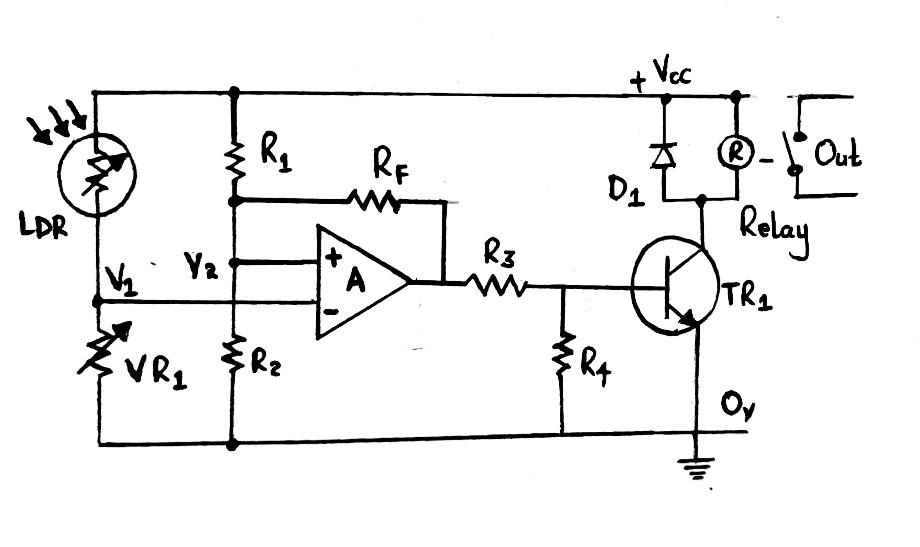
Circuit diagram on working of a light sensor circuit
From the above circuit,- VR1 (potentiometer) and LDR1 (light-dependent resistor) form a Wheatstone bridge – a resistance bridge network with an adjustable arm. Conversely, fixed resistors R2 and R1 form another component of the bridge network.
- Both arms of the bridge create potential divider networks crossway your supply voltage.
- Meanwhile, V2 and V1, the supply voltage outputs, respectively connect to inverting and non-inverting inputs of the op-amp.
- A differential amplifier/voltage comparator having feedback is the operational amplifier configuration. Further, the differences between V2 and V1 voltages/input signals determine the output voltage condition of the differential amplifier.
- Also, if you combine R2 and R1, you'll generate a fixed voltage reference at V2 (R1/R2 ratio).
- Then, at V1, you'll have the variable voltage after combining VR1 and LDR1. The voltage is proportional to the light level the photoresistor detects.
- D1 freewheel diode protects the relay of the op-amp's output controls.
Circuit Operation Summary
LDR will first sense the light level. The op-amp's output will activate the relay if the reference voltage at V2 is higher than its output voltage. The state will also switch the connected load. With the increase in the light level, the output voltage switches back, thus turning off the relay. You can use feedback/hysteresis resistor, Rf, to set the hysteresis between the two switching points.How to Build a Light Sensor Switch Circuit?
Here, we'll learn about an automatic daylight sensor switch and circuit diagrams you can employ in the DIYs.Using NOT gates and CMOS NAND gates to make a light-activated day dark switch
Our second project involves using CMOS ICs to achieve a day-dark switch circuit.Component's list
- D1 – 1N4007,
- P1 – 1M preset,
- R2 – 10k ¼ Watt,
- T1 – BC547,
- ICs – You can either use IC 4049 or IC 4093,
- R1 – Any LDR (light dependent resistor) with an approximate resistance of 10k to 50k in daylight will do,

(LDR icon)
- C1 – 0.1uF ceramic disc, and finally
- Relay – 12V, 400-ohms, 5 amp.
Using NOD and NAND gates in a circuit
Circuit Explanation
Begin by shorting both inputs together to form inverters from each logic gate. In that way, you'll effectually reverse the gates' input logic level at their outputs. Note; One NAND gate is often efficient in implementing the circuit's operation, but we've used three gates instead. They act as buffers and offer better results as well as reduce wastage. Then, you'll accompany the gate responsible for light sensing with the light-sensing device (LDR). The connection's such that you wire the LDR across the gate's input. You'll also place a variable resistor at the positive end. The variable resistor ensures the gate has a triggering point after the light falling on the LDR achieves is ideal. Subsequently, the input of the gate rises, the output lowers as the output of the buffer gates rise. That leads to a relay assembly and trigger on the transistor. Finally, the connected load starts performing its intended function.An automatic night-operated LED lamp circuit
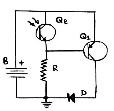
Our third circuit is quite complex, but following the guideline will make work easier for you. Here, the focus is to make something similar to flashlights manufactured with bright and highly efficient LEDs.Components required
- 1K resistor (one),
- 1 PNP BC557A (Q1),
- One battery 3V coin,
- One compatible phototransistor, and
- One super bright LED (white).
Circuit diagram of an automatic night-operated LED lamp circuit
Circuit explanation
A phototransistor helps the circuit operate even in darkness. As such, it'll switch ON the LED during nighttime. Additionally, you might only need one button battery type to ensure your circuit is compact. The phototransistor's emitter voltage stays high when ambient light falls on it, and it keeps the base of Q1 shut. However, during dark hours, the phototransistor loses its conduction. The emitter voltage drops and gradually shuts down. Next, Q1, through the ground/base resistor, R gets the biasing then increases light intensity deeper into the darkness. Furthermore, you can vary the R resistor value to achieve the desired ambient light level on LED in a switched-on state. Finally, the circuit may use 13mA as the LED lights up and some hundred when switching off the LED.Using transistors to make a light-activated day night switch
In our last project, we'll show you how to make a wiring configuration of a light sensor circuit using transistors.Hardware components
- Transformer – 0-12V/500mA or 1 amp (as a power source),
- C2 – 10uF/25V,
- C1 – 470Uf/25V,
- VR1 – 10k preset,
- All diodes – 1N4007,
- Relay – 12V, 400 ohms, 5 amp,
- R1, R2, and R3 – 4k ¼ Watt,
- T1, T2 – BC547,
- LDR - Any LDR with an approximate resistance of 10k to 50k under shade will do.
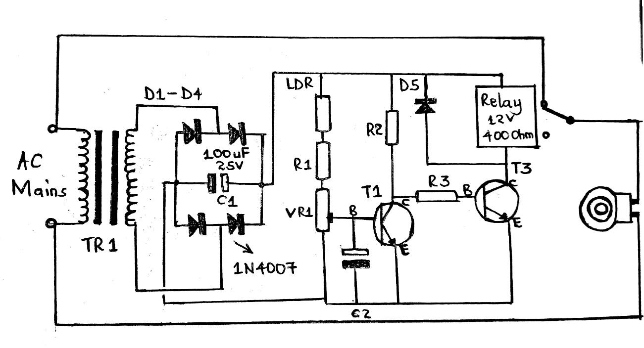
Circuit diagram of a light-activated switch using transistors
Circuit Operation
First of all, the transistors act as inverters. In other words, when you switch off T2, T1 switches on and vice versa. Similarly, when T1 is conducting, T2 switches OFF and consequently switches off the light or connected load. The contrary occurs in darkness. T1 operates as a comparator and comprises a positive supply via a preset and an LDR placed in its base. The LDR further triggers T1 if the light level surpasses the set threshold and senses ambient light conditions. Preset P1 sets the point. Using two transistors generally reduces the circuits. Why steres are that would have come about with only one transistor.Conclusion
Undeniablthere'se's a wide variety of sensors, one of them being a light switch sensor. The sensors often favor light sources like incandescent bulbs. Moreover, using them is advantageous because they have reduced energy costs and sustainable lighting control. You can also use light sensor circuits in many sensor-based applications like security alarm systems. For more information on light sensor technology, kindly contact us.Special Offer: Get $100 off your order!
Enjoy $100 off your order! No hidden fees and no minimum order quantity required.
Email sales@ourpcb.net to get started!
Email sales@ourpcb.net to get started!