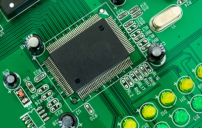
Everyone needs good quality music or sound when using a public address system. Therefore, this calls for a particular electronic device. If you have been looking for a device that will produce a well-balanced sound, a printed circuit board (PCB) preamp circuit will serve you well. However, many considerations have to be put in place during the PCB design and PCB assembly processes to ensure you get the best performance out of it.
Therefore, we are here to help you. Continue reading this article to learn more about the preamp circuit and how custom PCB manufacturing can enhance your audio experience.
Contents
- 1. What is a Pre Amp Circuit?
- 2. What is the Function of a Pre Amplifier?
- 3. What is the Difference Between Amplifiers and Preamplifiers?
- 4. How Do You Make a Preamp Circuit?
- Step 1: Assemble All Parts
- Step 2: Join All Components.
- Step 3: Fix the 100K Resistor
- Step 4: Fix the Capacitor
- Step 5: Join Again a Resistor and Capacitor
- Step 6: Again, fix a 10K Resistor
- Step 7: Fix a Mic to the Circuit
- Step 8: Join Each Other Left & Right of Aux Cable
- Step 9: Fix Battery Clipper Wire
- Step 10: Fix Aux Cable Wire
- Step 11: Connect Battery and Use It
- 5 preamplifier circuits
- Simple Pre-Amplifier circuit using two Transistors
- Simple Pre-Amplifier circuit using a FET
- Balanced Preamp
- Preamplifier with Tone Control
- Automatic Gain Control Preamplifier Circuit
- Conclusion
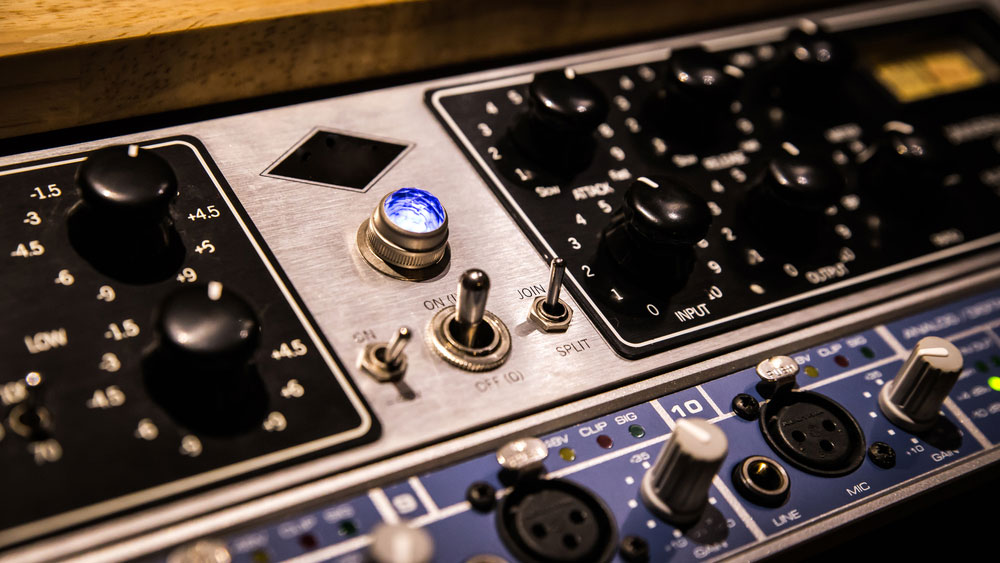
1. What is a Pre Amp Circuit?
Preamp circuit
A preamplifier circuit is an electronic circuit that changes a weak signal from a microphone, players, or sound pickups to a strong one. Alternatively, it strengthens a call to the required level. It acts as a link between a signal source and the power amplifier. Therefore, it becomes easy for the device to tap a weak signal that the power amplifier circuit cannot detect and immediately send it to the power amplifier. Moreover, you should place the preamplifier close to the sound source.
Moreover, you can tune and control the device using the front screen. At the back of the device are connectors that sync with an amplifier, record players, microphone, among other electronics. Although different electronics have different features, manufacturers ensure that this device fits all by fixing knobs on the device. Additionally, the knob increases or reduces timbre and adjusts the frequencies. Moreover, the knobs also act as volume control. Therefore, to have the best quality sound output, purchase both the high-quality amplifier and the best preamp.
2. What is the Function of a Pre Amplifier?
The primary function is to enhance signal level for it to be suitable for audio sources. Additionally, it equalizes the frequency made during recording since records come at low frequencies. Therefore, when playing music, the cartridge converts the mechanical signal into an electrical one.
Special Offer: Get $100 off your order!
Email [email protected] to get started!
3. What is the Difference Between Amplifiers and Preamplifiers?
As said before, the two devices are essential since they complement one another. Besides, there are several differences between the two. Therefore, below are the differences:
Firstly, a preamp enhances a weak audio signal to the required level, while an amplifier enhances the line level to the speakers.
Secondly, a preamp removes background noise through audio processing while an amplifier does not.
Finally, a preamp amplifies a signal from the antenna to avoid attenuation, while an amplifier provides more signals where numerous tuners are in use.
4. How Do You Make a Preamp Circuit?
Step 1: Assemble All Parts
Purchase all the items that you will require for the preamp circuit.
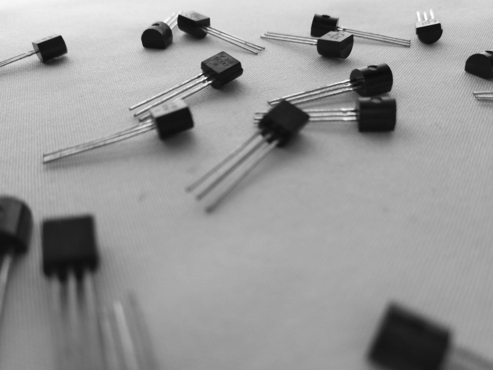
- Transistor BC547
- Capacitor - 16V 100uf

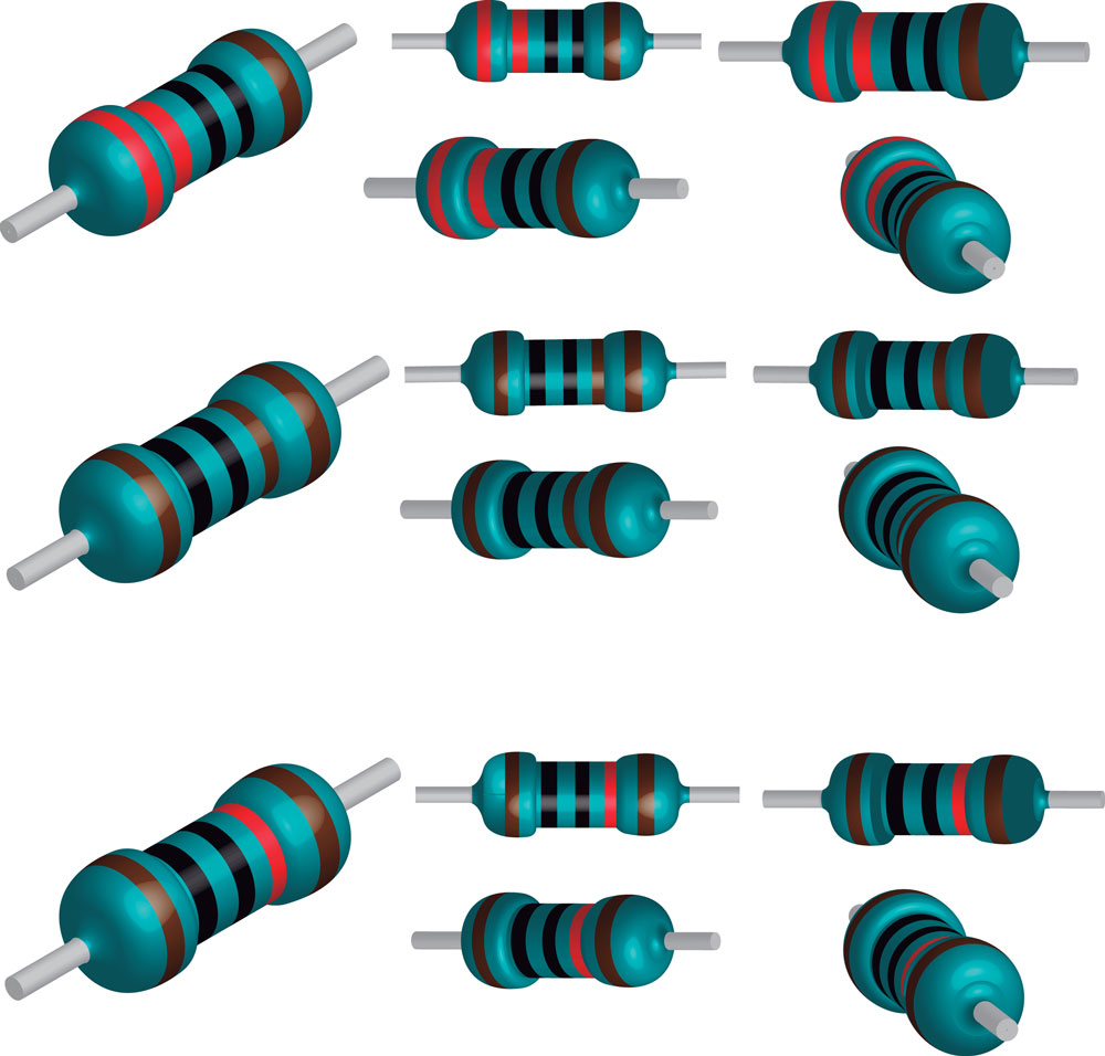
- Resistor - 100K
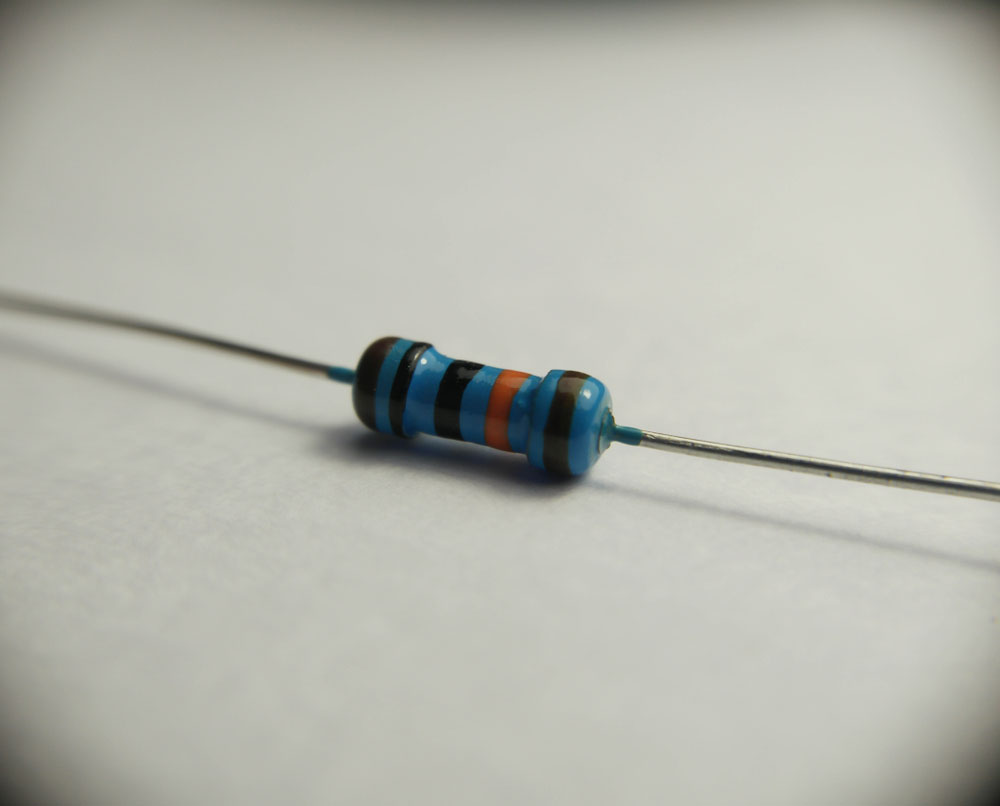
- Resistor - 10K
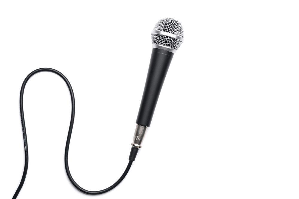
- Mic
- Audio input jack
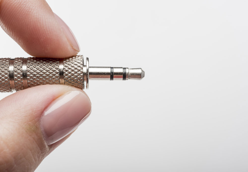
- Aux cable
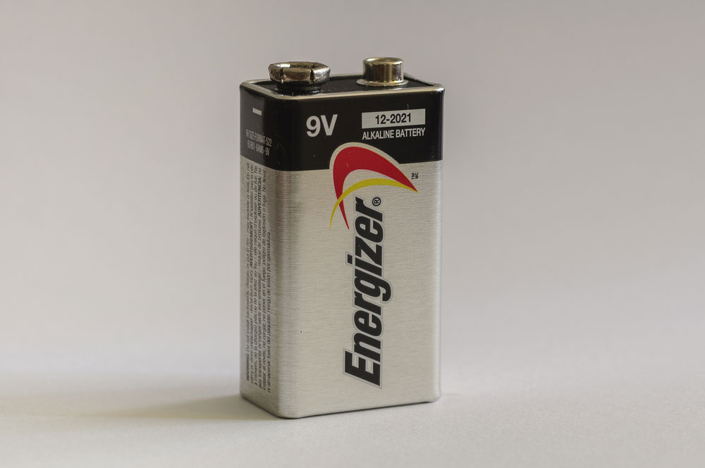
- Battery 9V power supply
- Battery clipper
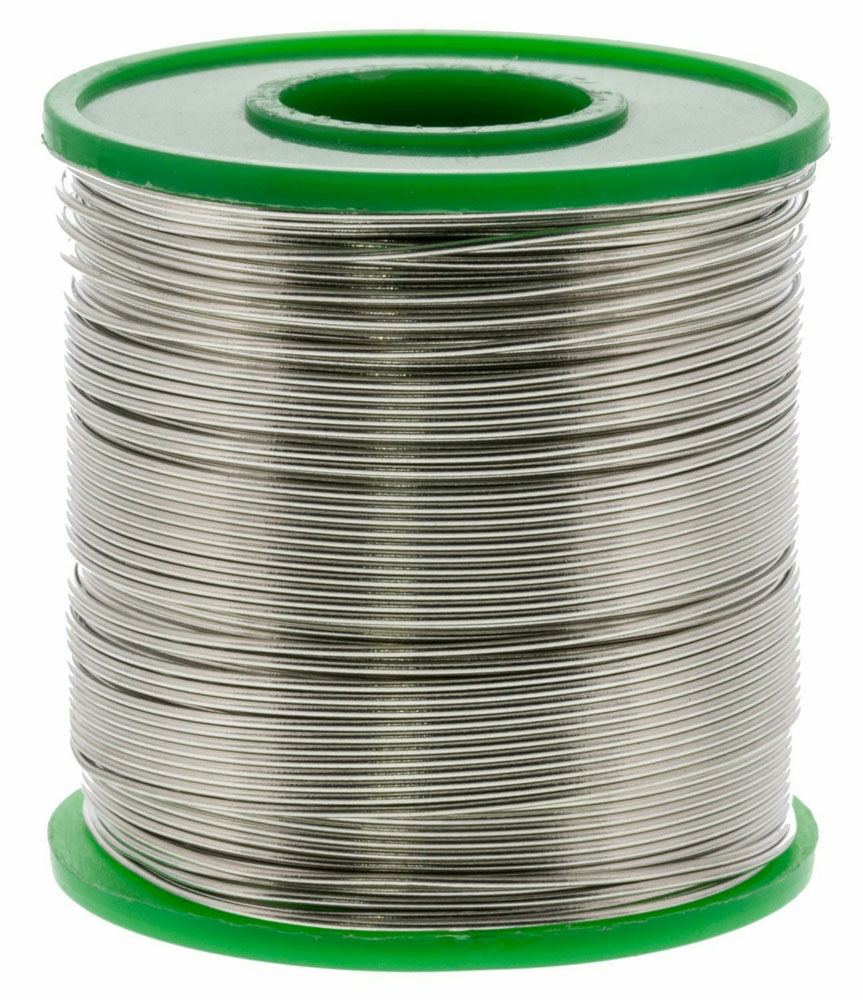
- Soldering wire
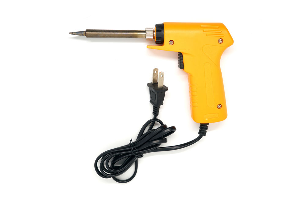
- Soldering gun
Step 2: Join All Components.
Join all the circuit components according to your circuit diagram.
Step 3: Fix the 100K Resistor
Fix the 100K resistor using the soldering wire at the base of the transistor.
Step 4: Fix the Capacitor
Fix the –ve terminal of the capacitor using the soldering wire at the transistor’s base also.
Step 5: Join Again a Resistor and Capacitor
First, join the +ve terminal of the output capacitor to the emitter of the transistor.
Secondly, fix a 10K resistor to the same part.
Step 6: Again, fix a 10K Resistor
Join a 10K resistor to the –ve side of the output capacitor fixed at the base of the transistor. Additionally, fix the other end of the resistor to the 10K resistor fixed in the emitter of the transistor.
Step 7: Fix a Mic to the Circuit
Fix the mic to the circuit and solder the –ve side of the mic to the collector. Finally, solder the +ve side of the mic to the positive terminal of the capacitor connected to the base.
Step 8: Join Each Other Left & Right of Aux Cable
Join each other L & W wire of the aux cable.
Step 9: Fix Battery Clipper Wire
Fix the battery clipper wire to the circuit.
Step 10: Fix Aux Cable Wire
Join the aux cable to the circuit using the soldering wire. Then, join the +ve side of the aux cable to the –ve of the capacitor connected to the emitter. Finally, fix the –ve side of the aux wire to the collector.
Step 11: Connect Battery and Use It
vehicle battery
Since our circuit is ready for use, connect the battery to the clipper. Secondly, plug in the aux cable. Then, set the amp in aux mode. Finally, speak on the mic and ask someone to listen to the speaker. Therefore, if there is sound from the speakers, then you are good to go.
5 preamplifier circuits
-
Simple Pre-Amplifier circuit using two Transistors
You can build a simple preamplifier circuit by connecting two transistors and resistors hence the name two-transistor preamplifier. Additionally, you should add a feedback loop to the circuit to improve the amplification.
Moreover, we all know that any music has a wavering frequency. Consequently, if such a wavering input signals costly through the end terminals, it is sent to the ground. Therefore, high amplitudes typically come out and then regenerate with a potential almost identical supply voltage.
This simple circuit boosts minimal frequencies to significant outputs for feeding large amplifiers. However, this circuit was popularly standard in old cassette playback devices for raising the signals. Moreover, this could make the work compatible with the high-power amplifier.
-
Simple Pre-Amplifier circuit using a FET
FET preamp circuit
The FET preamp circuit provides a massive boost to an AF signal. Its input stage doesn't use a common source but a standard gate instead. Additionally, it can work solely or like stage equipment calling for such capability. Moreover, the input impedance of a 2-stage FET preamp circuit is about one megaohm. Nevertheless, you can determine by the value of the input resistor. Although the overall gain of the circuit is about 100, it can still go a bit lower or upon some FETs.
Therefore, a FET preamp circuit can consume about 1.4 mA on a 12-volt direct current source in full working mode. However, this value can vary according to the specific features of the FETs.
-
Balanced Preamp
A balance preamp, also known as a differential amplifier, has two different inputs. Therefore, a sound course amplifier should perform several kinds of stuff. To construct this type of preamplifier circuit, you need a 100mV connection to a resistor. Moreover, this will provide you with a gain of nine. Besides, you can get an output signal of 900mV.
-
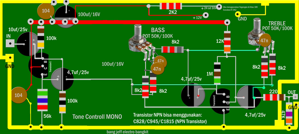
Preamplifier with Tone Control

Nevertheless, quality control can amplify the input to make it practical for an outstanding High-Frequency preamp circuit. Moreover, the audio tone control circuit has treble and bass characteristics for turning the quality of the output. Therefore, the best would be a system that can work two ways. That is, amplifying the input signal level and improving the quality of the output for the successive power amplifier stage.
-
Automatic Gain Control Preamplifier Circuit
An automatic gain control preamplifier circuit is a preamp circuit that works best on microphones. Additionally, it performs best on radio transmitter modulators and can fit intercoms and power amplifier systems to produce superb intelligibility. Besides, it comes with automatic gain control that keeps the output consistent and of high quality. Finally, the circuit can also work on inputs with a maximum input of up to 1V.
Conclusion
As we said initially, you should ensure that you get the best sound output from your system. Therefore, it makes no sense to have a costly procedure and get substandard sound qualities. However, next time you shop for a design, consider having a preamp circuit. Nevertheless, several preamplifiers have provided you with elaborated details on some of the critical things you should consider. Finally, you can visit ourPCB site to know more.
Special Offer: Get $100 off your order!
Email [email protected] to get started!