Even though the world is shifting to electric cars and motors, gas engines are still a big part of modern-day machines and won't disappear any time soon. One key component in these motors, especially the high-speed type, is the CDI ignition system.
If your project require using a gas engine, you need to understand how to make a CDI for easy designing into a PCB and how it works. We have covered these topics in detail below, so take a look! The device is quite common in motorcycles, where you'll find it under the seat.
Contents
- What Is A CDI Ignition?
- How Does A CDI System Work?
- Construction of Capacitor Discharge Ignition
- Flywheel and Stator
- Charging Coil
- Hall Sensor
- Timing Mark
- Trigger Circuit
- Different Types of CDI Ignition
- AC-CDI Module
- DC-CDI Module
- Which Is The Best CDI?
- Advantages of CDI
- Disadvantages of CDI
- How To Make A CDI Box?
- How the Circuit Works
- How Do I Test My CDI Ignition?
- How To Troubleshoot A CDI System
- Summary
What Is A CDI Ignition?
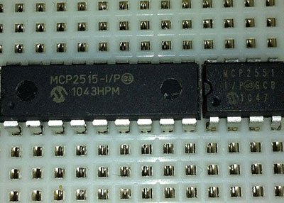
Also known as the brain box, pulse pack, or igniter box, A CDI (Capacitor Discharge Ignition) is a black box found that forms the core of the ignition system. Its function is to control the fuel injectors and spark plugs to ensure the engine runs smoothly. You will mostly get it in small engines, such as lawnmowers, chainsaws, motorcycles, and ATV dirt bike engines. But some cars and turbine-powered aircraft also have it.
Source: Wikimedia Commons.
The thyristor ignition is an improvement from the IDI (Inductive Discharge Ignition) because it has a shorter charging time, making it ideal for high-speed engines.
How Does A CDI System Work?
The primary component in a CDI is the capacitor, and the system passes current over it, building charge quickly. This power gets pumped into the ignition coils at just the right time to boost the spark energy output and ignite the engine.
From a more technical angle, the unit gets two voltage inputs, one from the alternator and the other from the pickup coil. The alternator delivers the high voltage (100-200V AC) while the pickup coil channels in a low voltage pulse (10-12V AC).
You can only charge a capacitor using DC, so the high voltage AC gets rectified, and the resulting DC goes into the high voltage capacitor.
The low voltage from the pickup coil drives a Silicon-Controlled Rectifier (SCR), which helps discharge the high voltage charge stored in the capacitor. This charge goes into the primary of the ignition coil. Therefore, the SCR acts as the trigger circuit or pulse coil.
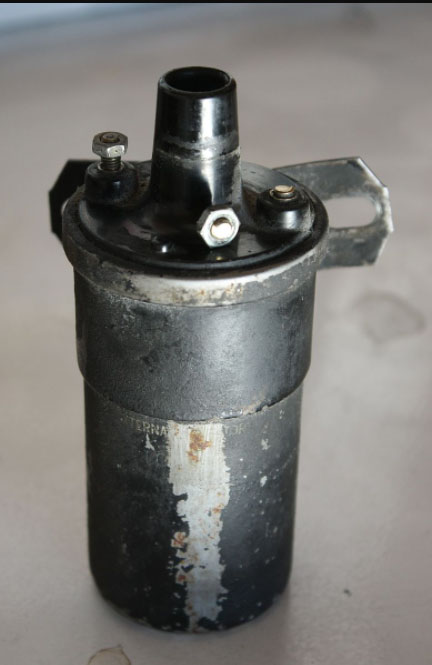
An ignition coil
Source: Wikimedia Commons.
Creating sparks requires a high voltage, and a CDI system delivers this power quickly with a short charging time. Ignition coils act as step-up transformers. When the high voltage charge from the capacitor gets to this point, the coil ramps it up to many kilo-volts then sends it to the spark plug.
Construction of Capacitor Discharge Ignition
A CDI contains multiple parts, all integrated with the ignition system. They include the following:
Flywheel and Stator
A CDI's flywheel consists of a large, permanent horseshoe magnet rolled into a circle. Its purpose is to turn on the crankshaft. On the other hand, the stator is a plate holding all the coils of wire required to switch on the ignition coil, battery charging circuit, and lights.
Charging Coil
As the name suggests, this coil is for charging, and it produces 6V to charge the capacitors. It is a part of the stator and generates power based on the flywheel's movement. This power then goes to the spark plug from the capacitors for fuel ignition.
Hall Sensor
The purpose of the hall sensor is to measure the hall effect, which is the instantaneous point at which the magnet in the flywheel changes poles. Remember, the flywheel spins the horseshoe magnet, so the polarity changes from north to south several times.
A hall sensor
Source: Wikimedia Commons.
When this switch occurs, the sensor sends a pulse to the CDI box, triggering it to dump the stored energy in the capacitor to the high voltage transformer (ignition coil).
Timing Mark
The timing mark is an arbitrary alignment point that indicates when the piston's top travel is equivalent to the stator and flywheel's trigger point. The stator plate and engine case share this point, and rotating the stator plate right or left changes CDI's trigger point.
Trigger Circuit
A trigger circuit usually consists of an SCR (Silicon Controlled Rectifier), thyristor, or transistor switch. It gets triggered by a pulse from the hall sensor and allows current only from one side of the circuit until the trigger event occurs. Once the capacitors fill up, the CDI gets triggered again.
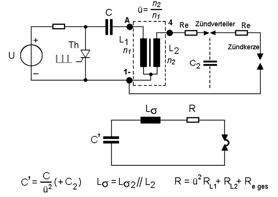
Capacitive Discharge Ignition: Equivalent Circuit Diagram
Source: Wikimedia Commons.
Different Types of CDI Ignition
CDI ignition modules come in the following two types:
AC-CDI Module
The power source for this module is the AC generated by the alternator. It is the most common CDI system used in small engines and usually goes under the magnetized flywheel.
Not all mini-engines have CDIs, though. Some have magneto ignition, while older motors from the 60s relied on an Energy Transfer system.
DC-CDI Module
Compared to the AC-DCI module, this one uses the battery as its power source. However, vehicles with this system have more precise ignition timing and can start the engine without issues when it is cold. Therefore, the system requires a DC/AC inverter to increase the capacitor DC discharge voltage from 2V to 400/600V.
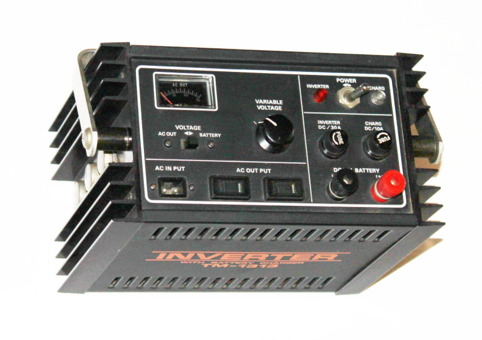
A large scale DC-AC inverter
Source: Wikimedia Commons.
Which Is The Best CDI?
None of the two modules is better than the other, but each is suitable for different applications. For instance, the AC-CDI has an uncomplicated design and is less likely to have issues. On the other hand, the DC-CDI is very effective in cold temperatures and gives accurate ignition timing.
Overall, the CDI is insensitive to shunts from the spark plug, and it can blaze multiple sparks in quick succession. This performance makes it ideal for a wide variety of applications.
Special Offer: Get $100 off your order!
Email [email protected] to get started!
Advantages of CDI
- Fully charges a capacitor in a short time, typically 1ms
- Insensitive to electrical shunts coming from spark plug fouling
- Fast transient response for the capacitor discharge ignition system
- Quick voltage rise
Disadvantages of CDI
- The CDI system produces harsh electromagnetic noises.
- The short but powerful spark is not good enough for igniting lean mixtures at low power.
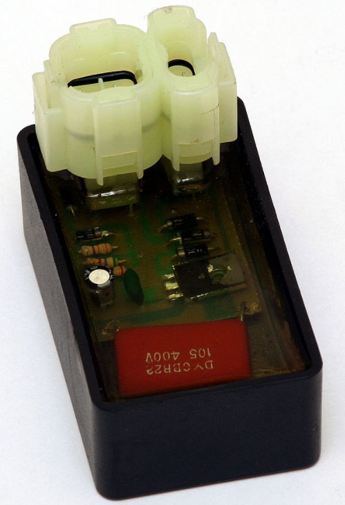
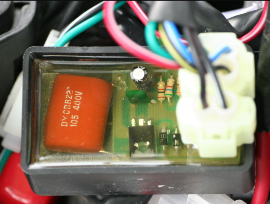
A Capacitor Discharge Ignition Module
Source: Wikimedia Commons.
How To Make A CDI Box?
The CDI box circuit is quite simple and is separate from the ignition coil. You need the following parts to build the course:
- Two resistors (5.6 and 56-ohm, 0.5W resistors)
- Three 1N4007, 1000V, 1A diodes
- One SCR (TIC106D, 5A, 400V)
- Two Mylar capacitors (2uF, 400V)
How the Circuit Works
A CDI box circuit diagram for a C90 Honda
As the flywheel rotates, it creates a magnetic field that cuts through the charging coil core, creating an AC voltage. This voltage flows across D3 in the forward bias, creating a DC electrical charge that powers up C1 and C2.
Since the current alternates, it flows through R1 to D1 and D3 on the opposite side in the negative half cycle. The current will also flow to the lead K of SCR1, then go through R2 to the lead G of SCR1. It still ends up charging the capacitors again during this cycle.
A voltage drop across R2 triggers the lead G of SCR1, making the circuit run. During the discharge, SCR1 sends the stored voltage to leads A & K and D2, then to the primary of the induction coil.
The magnetic field created by the voltage running across the primary coil induces a current on the secondary coil, which creates a high output voltage. This induced voltage goes out through the secondary coil to the spark plug and is strong enough to produce a powerful spark on the arc gap.
However, no electric current goes the ignition coil's primary when SCR1 is not running. Therefore, this ignition system component acts as a trigger for the ignition box.
SCR1 runs during ignition timing or when the piston stroke is up to the maximum level so that the spark ignites the air-fuel mixture at the right time.
The process occurs continuously to keep the engine running. But if you want to stop it, close the switch SW. Current will flow into the ground and stop SCR1 from running. This grounding halts the triggering of charge release from the capacitors.
How Do I Test My CDI Ignition?
There are different testing tools for checking the performance of the CDI box, but the most common ones are using an oscilloscope or a multimeter.
An oscilloscope
Source: Wikimedia Commons.
A digital multimeter
How To Troubleshoot A CDI System
Troubleshooting a CDI system is tricky, but it is usually the cause of most electrical issues in the engine. Therefore, you can know the box has a problem if you encounter the following topics:
- Misfiring
- Backfiring
- Rough running
- Engine starting issues
- Dead cylinders
- Stalling engine
- Rough running
Summary
In conclusion, CDI systems are critical devices in high-speed engines. Their capacitor design ensures they store enough charge quickly and release a powerful boost to the ignition coil at the correct ignition timing.
If you need such a device for your project, the circuit diagram above should guide you in the design process. Contact us if you need further clarification, and we will assemble the circuit board for your work at a reasonable price.
Special Offer: Get $100 off your order!
Email [email protected] to get started!