Arduino boards are handy for prototyping & development, and there are several boards you can use for your project. If you are looking for a compact Arduino microcontroller with breadboard compatibility, the Pro Micro is one of the best options. If you are unfamiliar with the board, this article covers the Arduino Pro Micro Pinout to explain the functions of each pin. Take a look!
Contents
What is an Arduino Pro Micro
Arduino Pro Micro is a microcontroller board based on the ATmega32U4 processor. It features native communication over USB, 18 digital input/output pins, a 16 MHz crystal oscillator, an ICSP header, and a reset button.
Therefore, it contains everything required to support the micro board, and you can get started by plugging it into a computer using the USB connector. And its form factor makes it breadboard-friendly.

An Arduino Pro Micro
This board is similar to the Leonardo because it features a built-in micro USB port that eliminates the need for a secondary processor. Therefore, it appears as a keyboard, mouse, standard Arduino, or virtual COM/serial (CDC) port when plugged into a computer.
Arduino Leonardo Compatibility
The Pro Micro boards come in the following varieties.
- 5V at 16MHz
- 3.3V at 8MHz
The 5V board is compatible with Leonardo, but the 3.3V is not. This version operates at half the speed to be in the safe operating zone at the low input voltage.

Different Arduino microcontrollers
A Pro Micro's operating voltage determines the maximum voltage allowed on the I/O pins. And you'll also have to differentiate between the two when uploading code to the device via the Arduino IDE.
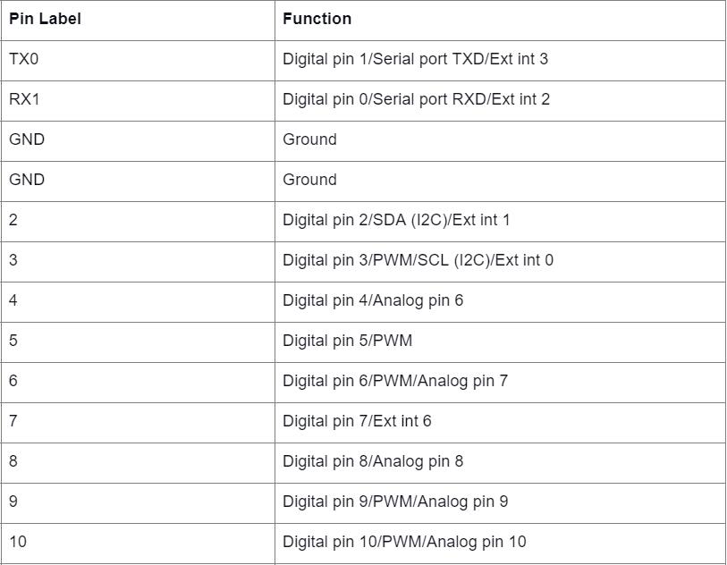
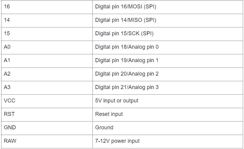
Arduino Pro Micro Pinout
Arduino's Pro Micro has 24 pins that generally fall into these two categories.
Power Pins
There are six power pins.
- RAW: This is an unregulated voltage input pin. If you power the board via the micro USB port, this pin's voltage will be 4.8V (5V minus the Schottky diode voltage drop). But if you power it externally via this pin, you can use up to 12V.
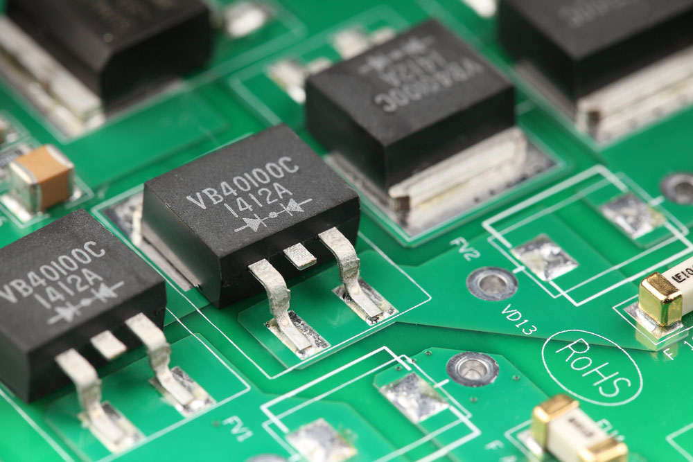
Schottky diodes and rectifiers mounted on a circuit board.
- VCC: This voltage pin supplies power to the board and can either be 3.3V or 5V, depending on the version. The voltage applied to the RAW pin regulates the one on this pin. And if powered via the RAW or micro USB port, you can use the VCC to supply power to other electronic devices.
- RST: The RST pin functions like a reset button that restarts the microcontroller. A 10kΩ onboard resistor pulls the pin and is active when low. Therefore, you should connect it to the ground to reset it. And the microcontroller will remain off until you pull the pin back to high.
- GND: Three pins provide the ground or 0V reference for the Pro Micro.
For more detailed setups, particularly involving SD card connectivity, understanding the SD card pinout is crucial when integrating storage devices for data logging or other applications.
I/O Pins
A total of 18 interfaces form the I/O pins and have a multi-functional design. You can use these pins to read a button press, as a digital I/O, or to blink LEDs.
Nine of the 18 pins have analog-to-digital converters, making them analog inputs. Five have pulse width modulation functionality that allows a form of analog output. These PWM pins have a faint circle around them on the board.
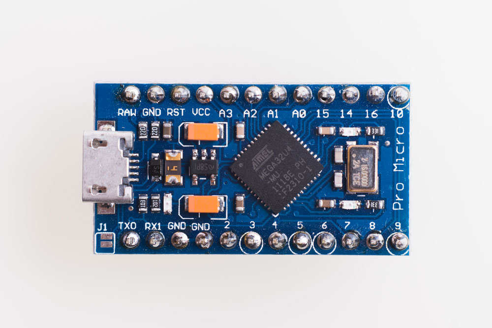
The Arduino Pro Micro. Note the rings around the pins with PWM functionality.
Also, there are hardware pins SPI, I2C, and UART (serial) for interfacing with digital devices like IMUs, LCDs, and XBees.
Besides the 24 pins, there is a J1 jumper for bypassing the 3.3V regulator in the 3.3V Pro Micro version and three onboard LEDs.
A voltage regulator module on a PCB
Pinout Summary
Arduino Pro Micro Tech Specs

Special Offer: Get $100 off your order!
Email [email protected] to get started!
How To Power the Arduino Pro Micro
The conventional way of powering the Pro Micro is via USB. This connection brings in 5V, and the 3.3V board will regulate it internally. So you can connect the other end of the USB cable to a computer, USB wall adapter, or USB hub.

An Arduino project with several components connected on a breadboard
Alternatively, you can use the RAW or VCC pins. If using the RAW pin, the board will regulate it to the correct voltage (3.3V or 5V). But don't let it exceed 12V. It should be at least 1V higher than the board's operating voltage (4.3V or 6V) to be on the safe side.
With the VCC pin, the power flowing in does not undergo any regulation. So only use it if you have a clean, regulated power supply that matches the board's operating voltage.

An Arduino board powered by a battery.
RAW and VCC options are ideal for projects using a battery pack as the power supply.
Arduino Pro Micro Applications
- Automatic pill dispenser
- USB joystick and trackpad
- Electric bike
- Water level meter
- Wireless keyboard
- Lock and unlock applications on Windows PCs
Wrap Up
In conclusion, the Arduino Pro Micro has two primary advantages. It is compact & breadboard friendly and offers native USB communication. And its pinout is relatively straightforward, as shown above. If you need further assistance for your projects, like PCB or PCBA, reach out, and we'll answer all your questions.
Special Offer: Get $100 off your order!
Email [email protected] to get started!


