The Raspberry Pi Foundation is known for developing some of the best single-board computers in the market. So they took the microcontroller world by storm when they released their first microcontroller unit in 2021. But the Pico is not like any other MCU because it features programmable IOs. We will define these inputs/outputs and how you can program them for your project. But first, let's briefly look at the Raspberry Pi Pico to cover the base.
Contents
What Is the Raspberry Pi Pico?
Raspberry Pi Pico is one of the most affordable microcontrollers, making it ideal for beginners. The unit is officially known as the RP2040, which refers to the name of its onboard chip. Raspberry Pi developed this chip internally under the Raspberry Silicon guise, and the Pico is the development kit for the RP2040 chip. This dev kit has several features, including a wide array of I/O options, such as programmable I/Os.

A vector image of the Raspberry Pi Pico
Special Offer: Get $100 off your order!
Email [email protected] to get started!
What Is Programmable IO?
Single-board computers and microcontrollers, like the Pico RP2040, support communication protocols like SPI, UART, and I2C to communicate with peripheral devices.
However, these protocols are not ideal when building projects involving legacy technologies with unknown interfaces. Also, it is impossible to use the known interfaces when building a solution requiring multiple SPI devices on a single MCU. But these projects can be done using programmable IOs.
The term refers to programmable input/output, and the pins enable you to create custom interfaces from scratch. Theoretically, you can build non-existent interfaces that are not in the market.
Technically, a PIO instance is like a tiny processor that runs code separately from the primary processor. So instead of using bit-banging protocols and CPU cycles, PIOs transmit and receive signals independently of the CPU. 
A complete PIO instance
Each PIO instance has four state machines, and each state machine accesses a shared instruction memory to run stored instructions. This memory can hold 32 instructions. Each state machine can run any of these instructions and control the GPIO pins.
Programmable IO State Machine Infrastructure
Every state machine has two FIFO structures, one for incoming and the other for outgoing data. The input FIFO is known as RX FIFO, while the output is known as TX FIFO.
When sending data to a GPIO pin using a state machine, you push the data to the FIFO input. The state machine will pull data from the queue and run the instruction when it is ready to process this data.
The advantage of this mechanism is that you can run the instructions independently without needing the central CPU. Instead, state machines run the system.
And although each FIFO can only hold four data words (32 bits), you can connect them with DMA (Direct Memory Access) to send larger chunks of data. Using DMA further frees the CPU from handling the process.
Scratch and Shift Registers
In the PIO block diagram above, the arrow from the FIFO to the state machine indicates the input. FIFO input links to the state machine via an input shift register (ISR). And there's an output shift register (OSR) between the state machine and FIFO output (arrow pointing to FIFO).

A shift register
The state machine also has two scratch registers for storing temporary data. Think of them as X and Y variables when programming these PIOs. 
Scratch and shift registers in a state machine
How To Program the Raspberry Pi Pico (RP2040)
The Pico SDK has the libraries, headers, and build system required to write programs for the RP2040 in C, C++, or assembly language. With C or C++, you need a CMake file to tell the Pico SDK how to convert the code into a binary application for the RP2040. But with Python programming, you only need an editor like Thorny and install MicroPython on the dev board.
With either option, the PIO assembler parses the PIO program file and outputs assembly code.
Programmable IO State Machine/Assembly Instructions
Assembly language instructions are complex, so most developers prefer using C, C++, or python. But we will briefly go through these instructions to give you a glimpse of what the low-level code does.
There are nine assembly language instructions for state machine control. They include.
- IN: Shifts one word of the 32 bits at a time from another location (like the scratch register or pins) into the input shift register
- OUT: Shifts one word of the 32 bits at a time from the output shift register to another location
- PUSH: Sends data to the input or RX FIFO from the input shift register
- PULL: Gets data (32-bit words) from the output or TX FIFO to output shift register
- MOV: Moves data from source to destination
- IRQ: Clears or sets the interrupt flag
- SET: Writes data to the destination
- WAIT: Stalls code execution until a particular action or condition occurs
- JMP: A conditional or non-conditional statement that transfers the code execution flow to another point by altering the instruction pointer register.
Programmable IO: LED Blinking C/C++ Code
You need the following components for C programming for your PIO application.
- A PIO program
- Software (C-language based)
- A CMake file to define how the two programs above get combined into a program image before loading into the RP2040 dev board
We will use this hello. Pio code that blinks the LED onboard the board using the pull instructions (32-bit word data from the TX FIFO) and programmable IOs.

Code for the hello. c program for blinking an LED
The code blinks the LEDs with a one-second complete cycle. It will turn the LED on for 500ms, then off for 500ms, completing one second. But you should load the program into the instruction memory before the state machines can run it. This responsibility falls into the pio_add_program() function, which looks for free space for the program in the PIO's instruction memory. Once it finds space, it loads the program.
The hello. Pio assembly code file has the required helper functions to set the C code.
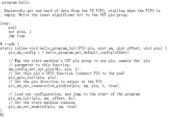
Code for the hello.Pio program to set the C code
You'll also need the CMake file to define how these two files get built into binary code that the Pico dev board can understand.
LED Blinking Python Code
There's no equivalent code in python for the C example above, but here is a simpler MicroPython code.

Code for the MicroPython program to blink an LED
Python programming for the RP2040 does not require a separate .pio file because the MicroPython and assembly code are in the same file.
Wrap Up
In conclusion, the Raspberry Pi Pico is the ideal microcontroller for working with non-standard peripherals due to its programmable IOs. Additionally, these I/Os can execute programs simultaneously to support VGA or other interfaces that require high-speed data transfer. But their non-standard interface communication is their primary advantage. So if you need to connect your board to unknown or unavailable communication protocols, get the Pico RP2040. And you can contact us to get the board or any accessories required for your project.
Special Offer: Get $100 off your order!
Email [email protected] to get started!