
0% complete
Blogs
TL072 Pinout: Pin Configuration, Specs, and Applications
A TL072 pinout guide covering pin configuration, key specifications, and applications of this low-noise JFET op amp, with a clear diagram.

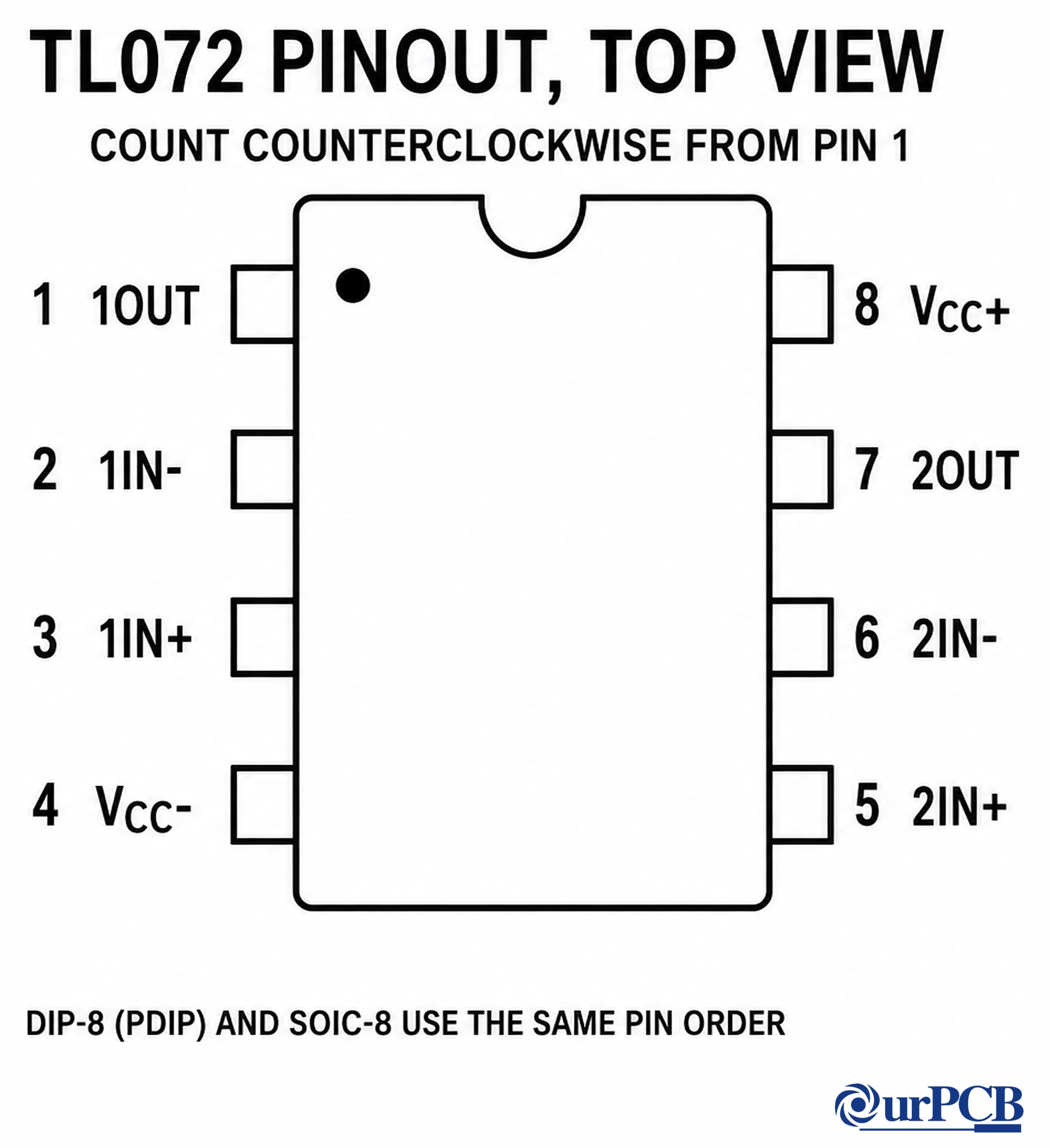
Viewed from the top, TL072 DIP-8 and SOIC-8 packages share this order: 1OUT, 1IN−, 1IN+, VCC−, 2IN+, 2IN−, 2OUT, and VCC+. Find pin 1 beside the manufacturer's pin-one index mark, then count counterclockwise.
| Pin | Name | Function |
|---|---|---|
| 1 | 1OUT (Output A) | Amplifier one output |
| 2 | 1IN− (Inverting Input A) | Amplifier one inverting input |
| 3 | 1IN+ (Noninverting Input A) | Amplifier one noninverting input |
| 4 | VCC− | Negative supply rail |
| 5 | 2IN+ (Noninverting Input B) | Amplifier two noninverting input |
| 6 | 2IN− (Inverting Input B) | Amplifier two inverting input |
| 7 | 2OUT (Output B) | Amplifier two output |
| 8 | VCC+ | Positive supply rail |
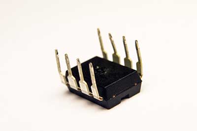
What Is the TL072?
The TL072 is a low-noise, FET-input dual operational amplifier. Two independent amplifiers share the VCC+ and VCC− supply pins inside one package.
The TL072 has no offset-null pins. Its eight pins serve two inputs and one output for each amplifier, plus the two supply rails.
The TL071 is the single-channel sibling, and the TL074 is the quad sibling. Their channel counts and package pinouts differ from the TL072.

TL072 Specifications and Functions
Use specifications only with their stated package, supply, load, and temperature conditions. A value copied without those qualifiers can misstate circuit capability.
TL072 functions
- Two independent operational amplifiers share one package and two supply rails.
- FET input stages provide high input resistance and low input current.
- Output short-circuit protection applies under the datasheet's stated condition.
TL072 electrical specifications
Values below come from the current Texas Instruments TL07xx datasheet. The combined document covers several dies, suffixes, and packages.
| Parameter | Datasheet value | Condition or scope |
|---|---|---|
| Channel count | 2 channels | TL072x device family |
| Recommended total supply | 10 V to 30 V | NS and PS packages, plus TL072M |
| Recommended total supply | 4.5 V to 40 V | Other devices in the current combined TI datasheet; verify the full suffix |
| Maximum peak output swing | At least ±12 V | VCC± = ±15 V, RL = 10 kΩ, and TA = 25°C |
| Maximum peak output swing | At least ±10 V | VCC± = ±15 V, RL ≥ 2 kΩ, and TA = full range |
| Output current | No single fixed maximum | Use load-dependent output swing and the typical output-current curves |
| Output short circuit | Continuous | Short to ground, one amplifier per package |
| Slew rate for TL07xC devices | 20 V/µs typical, 8 V/µs minimum | VCC± = ±15 V, VI = 10 V, CL = 100 pF, RL = 2 kΩ, and TA = 25°C |
The combined datasheet also warns that supplies above 36 V single or outside ±18 V dual can permanently damage the device. Confirm the exact suffix and package before selecting rails.
How to interpret TL072 output current
The datasheet does not define one guaranteed maximum load current. It specifies output capability through load-dependent voltage swing and typical current curves.
Do not treat the often-copied 10 mA figure as a guaranteed maximum. Check the required output voltage, load impedance, temperature, and exact part suffix.
Continuous short-circuit protection is not a normal operating-current rating. The stated condition is a ground short on one amplifier per package.
Where to Use the TL072
The TL072 suits signal-conditioning stages that benefit from FET inputs and low noise. TI lists professional audio mixers, inverters, motor drives, UPS systems, and battery test equipment as applications.
Use it as an operational amplifier with feedback. It is not a dedicated voltage comparator, and its output is not rail-to-rail.
How to Use the TL072
Choose the exact TL072 suffix and package first. Then connect each channel from the top-view pin table and keep the input traces short.
Place low-ESR, 0.1 µF ceramic bypass capacitors close to the supply pins. Separate sensitive input traces from supply and output traces.
Check the input range, output swing, load, and supply limits before finalizing the circuit. If a positive rail uses a regulator, verify its 7812 pinout before layout.
Applications
- Professional audio mixers
- Solar string and central inverters
- AC and servo motor-drive control
- Single-phase and three-phase UPS systems
- Battery test equipment

TL072 Family and Substitution
TL071, TL072, and TL074 identify single, dual, and quad channel counts, respectively. They are related devices, but they do not share one package pinout.
Do not substitute a sibling by name alone. Confirm channel count, package, supply range, input range, output requirements, and every pin before changing a design.
TL072 Application Circuit
The circuit below shows one operational-amplifier channel in an inverting configuration. For amplifier one, the signal enters pin 2, and feedback returns from pin 1.
Pin 3 provides the noninverting reference. The second channel remains available on pins 5, 6, and 7, while pins 4 and 8 power both channels.

TL072 Operating and Layout Checks
- Confirm the full part suffix and package before choosing the supply rails.
- Keep the input voltage inside the datasheet range for that device version.
- Verify output swing at the intended load instead of assuming a fixed current limit.
- Place supply bypass capacitors close to the IC and minimize sensitive trace length.
- Do not use short-circuit protection as a normal operating mode.
Summary
The TL072 is a dual FET-input operational amplifier with two channels and shared supply pins. Its DIP-8 and SOIC-8 pin order is identical when viewed from the top.
Use the pin-one index before counting, and do not expect offset-null pins. Apply supply and output values only with their datasheet conditions.
Need help preparing a board around this device? Contact OurPCB to discuss fabrication and assembly requirements.
Step 1 of 3
Get a free quote
What can we build for you?
PCB project ready?
Get a free quote