Various power supplies exist on the market today. Each of them provides unique characteristics and capabilities for everyday applications. But you may feel a little uncertain about which one to implement for your electronic circuit. For this reason, we will explore the switch mode power supply. In general, this device converts the input AC it receives into another form, relying on particular components for this process. As a result, you can expect the power supply to output the correct level for your device. We put together this guide to help you understand an SMPS circuit better. So let’s take a look!
Contents
- What is SMPS?
- Types of SMPS
- AC to DC Converter
- DC to DC Converter
- Flyback Converter
- Forward Converter
- Working Principle of SMPS Circuits
- Advantages and Disadvantages of SMPS
- SMPS Applications
- Simple SMPS Circuits
- Simple switching power supply circuit
- Single-ended forward switching power supply circuit
- Push-pull switching power supply circuit
- Summary
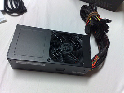
What is SMPS?
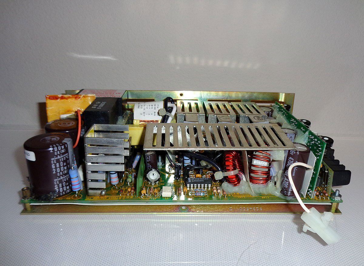
(a switched-mode power supply.)
Switch Mode Power Supply (SMPS) is an electronic power supply unit. It converts a voltage AC level into the required form for varying applications through a high-frequency switching transistor. This device also features components, such as diodes, inductors, semiconductors, capacitors, etc. The unit has three other names: switched-mode power supply, switcher, or switching mode power supply.
Additionally, an SMPS has common applications in electronics that rely on a highly efficient and stable power supply to operate. A device will generally require a maximum power of 150W to utilize an SMPS. Some circuits may also include a bridge rectifier to help eliminate electrical noise.
Types of SMPS
We listed four main SMPS types below, which provide different input power delivery methods to the connected load.
AC to DC Converter
Simply put, an AC to DC converter transforms alternating current (AC input) into direct current (DC). It relies on a combination of rectifiers and filters to achieve this process.
DC to DC Converter
The DC to DC converter (electrical or electromechanical device) converts a DC voltage type into another DC level. And it also serves as an electrical power level converter.
Flyback Converter
A flyback converter is ideal for applications with low power requirements. That’s because the output generates a very low voltage (under 100W) regardless of the input voltage. Plus, these typically rely on a flyback transformer.
Forward Converter
The forward converter generates an output DC voltage through an unregulated DC input source. It operates similarly to a fly-back converter but relies on different switch control devices.
Working Principle of SMPS Circuits
(Switch mode power supply. Source: Wikimedia Commons)
A rectifier or battery supplies input supply voltage to the inverter. And this triggers it to switch on and off at high frequencies (20KHz-200KHz) via a power transistor or switching MOSFET. Afterward, the transformer’s primary winding receives these high-frequency voltage pulses. In turn, the secondary AC output rectifies and smooths via a bridge rectifier, generating a constant voltage. Then, a control circuit changes the duty cycle until it reaches the desired output level.
Half-bridge, flyback, push-pull, and full-bridge topologies feature a transformer responsible for output voltages, electrical isolation, and voltage scaling. However, non-isolated topologies lack a transformer, so the inductive energy transfer performs the conversion.
An SMPS also provides high efficiency due to its ability to control the output. And this occurs via input switching rather than dissipating excess power as heat.
Special Offer: Get $100 off your order!
Email [email protected] to get started!
Advantages and Disadvantages of SMPS
We listed the main advantages and disadvantages of an SMPS below:
Advantages:
- High efficiency, between 60% to 95%
- Lightweight and compact
- Generates less heat
- Minimal power loss
- Inexpensive manufacturing costs
- Low power consumption
- Lower harmonic feedback in the mains supply
Disadvantages:
- High-frequency switching produces noise
- Complex circuit
- Generates electromagnetic interference
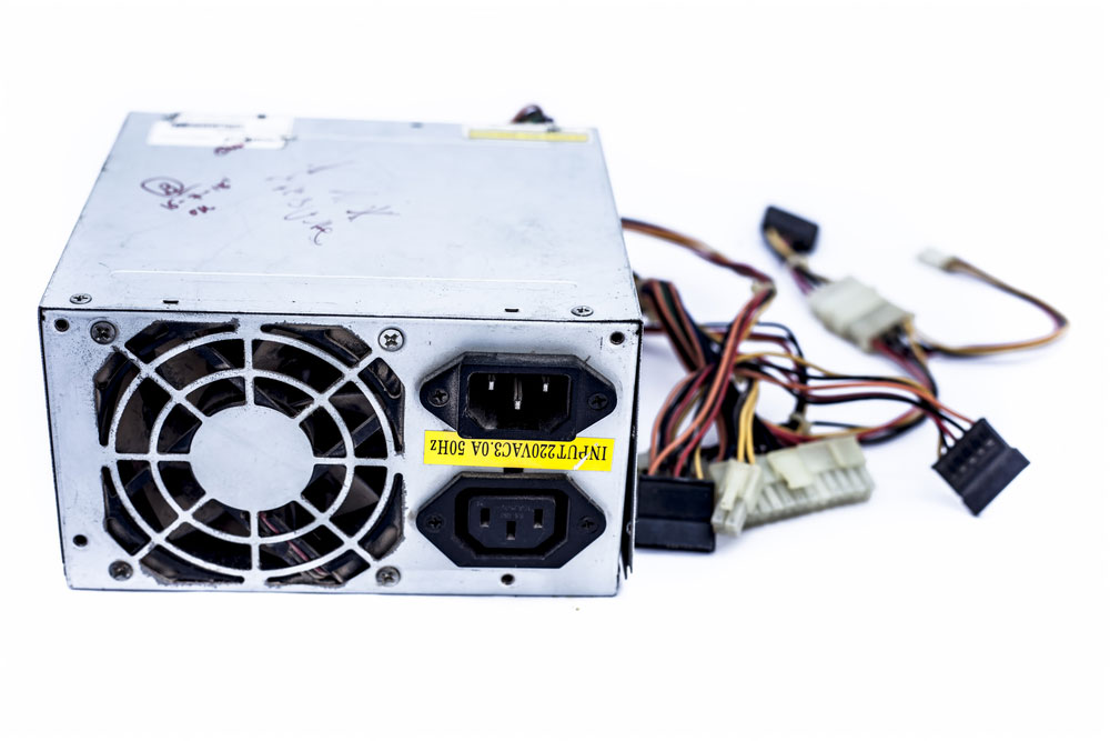
SMPS Applications
(A personal computer features an SMPS.)
Generally, an SMPS circuit has varying applications. We listed a few of them below:
- Power amplifiers
- Personal computers
- Motor drives
- TV sets
- Security and railway systems
- Mobile phone chargers
- Space stations
- Laptops
- Battery chargers
- HVDC measurements
Simple SMPS Circuits
You can take a look at three SMPS circuits below:
-
Simple switching power supply circuit
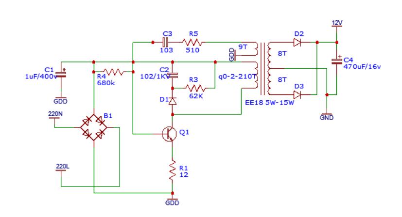
(Circuit diagram of a simple switching power supply.)
The simple switching power supply circuit, as shown above, can fully operate with a few components. Generally, it allows you to adjust the oscillation frequency between 30KHz to 45KHz, achieved through C3 and R5. Additionally, the circuit generates a stable output voltage and allows the output current to reach 500mA. Overall, it provides power at 8W with an efficiency of 87%.
-
Single-ended forward switching power supply circuit
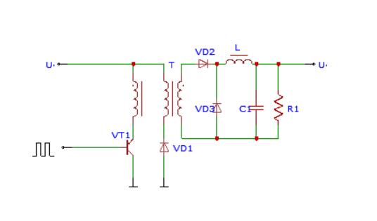
(Single-ended forward switching power supply circuit.)
Although the circuit looks like a single-ended flyback circuit, it operates in a different setting. The switch tube’s (VT1) activation will trigger the VT2 to activate as well. Afterward, the transformer supplies the load with power, which then gets stored in the inductor.

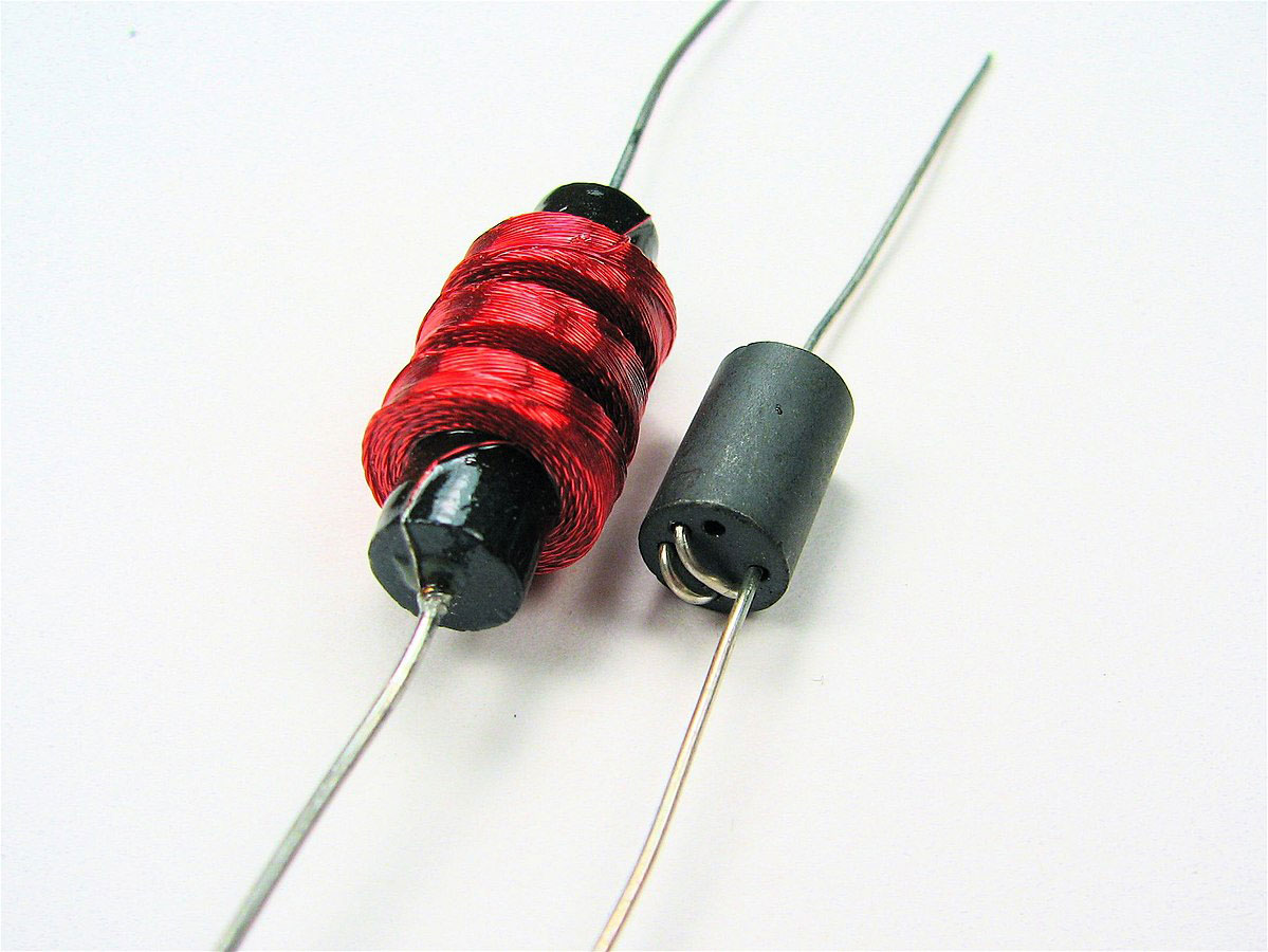
(The inductor stores and releases energy.)
Then, the inductor releases stored energy into the load once VT1 deactivates. This energy flows through a freewheeling diode, VD3. Additionally, the circuit features a clamping coil and VD2 diode. Generally, this diode restricts the VT1’s maximum voltage to half of the power supply’s voltage. Moreover, the reset time and flux establishment must match to perform the magnetic core reset condition. As a result, the circuit’s duty cycle pulse needs to stay below 50%.
Overall, the circuit generates an extensive power range, rated between 50-200W. While that may seem like a sufficient amount, the circuit only has a few applications. And that’s because the transformer features a complex build and large volume.
-
Push-pull switching power supply circuit
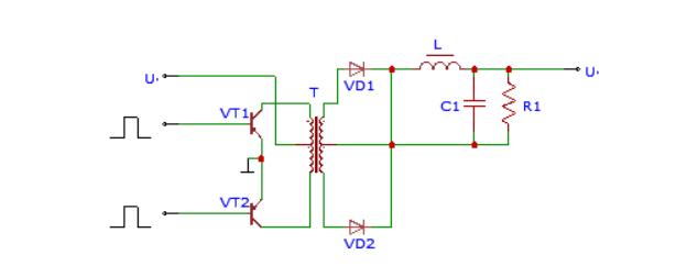
(Circuit diagram of a push-pull switching power supply.)
The above diagram illustrates a push-pull switching power supply circuit. It consists of a transformer that operates on two of the hysteresis loop’s sides. In general, the double-ended conversion circuit features two switch tubes, VT1 and VT2. Both of these alternatively activate and deactivate in response to the square wave signal’s excitation. The transformer’s secondary winding draws in the voltage. Afterward, it undergoes rectification to adjust to an appropriate DC voltage level.
Both the switching tubes provide an advantage because they can easily drive voltage. However, a disadvantage also applies here due to the switching tubes' ability to withstand only double the output voltage. Overall, the circuit produces an extensive power range, rated between 100-500W.
Summary
Overall, an SMPS circuit adjusts the mains voltage level, making it more suitable for your electronic devices. It usually relies on some components to achieve the process. However, some types do not feature the same configurations due to each of their intended purpose. For example, a flyback converter will output under 100W of power, making it ideal for low-power devices. And this relies on a transformer, which a non-isolated power supply lacks, to perform the conversion process.
Do you have any questions regarding an SMPS circuit? Feel free to contact us!
Special Offer: Get $100 off your order!
Email [email protected] to get started!