What is the motor driver? A motor is an electronic device that helps convert electrical energy into mechanical energy. Therefore, a motor driver allows you to conduct automatic works using electrical power. We have several different kinds of electric motors. These types include the DC motors, the stepper motors, and the Servo motors. Their working principles and characteristics are the differentiating factors among these motors. Choosing the correct type of motor driver is essential because it allows your engine to work efficiently with the microcontroller of your choice. This article will help you understand how the motor driver works, the characteristics, types, and essential components when making connections. Let's begin!
Contents
- What is a Motor Driver?
- What are Characteristics of Motor Drivers?
- Compatible Motors
- Interface
- Voltage and Current
- What are the Main Components of Motor Drivers?
- What are the Different Types of Motor Drivers?
- Example of a Stepper Motor Driver System: NEMA 17 Stepper Motor
- How Does the Motor Driver Work?
- Why Do You Need a Motor Driver?
- What is an H-bridge Circuit?
- How to Build Motor Driver Circuits
- What Do You Need To Build A Motor Driver Circuit?
- Source: Wiki Commons
- What are the Steps to Build A Motor Driver Circuit?
- What Are Some Applications of Motor Drivers?
- Robotics and Automation Systems
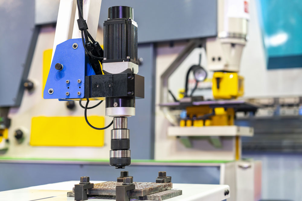
- Computer Numerical Control (CNC) Machines
- 3D Printers and Other Additive Manufacturing Equipment
- Automotive Systems (Power Windows, Sunroofs, etc.)
- Industrial Machinery and Equipment
- Summary
What is a Motor Driver?
From the name, a motor driver means a device that drives motors. However, motor driver chips can't go an engine without a microcontroller.
A motor driver showcases itself as an interface between the motor and the microcontroller. The reason is that the microcontroller and the motor work on different ranges of voltages. The engine will use up a higher current level than the microcontroller.
You require a motor driver module when connecting two devices that operate under different current levels to a power supply voltage. In this case, a motor acts as a third device that steps up or steps down the voltage supply.
The majority of motor drivers in the market now are in the form of ICs. There are different driver motors; hence they have other characteristics. You then connect these motor driver ICs to the motor controller through an H bridge circuit.
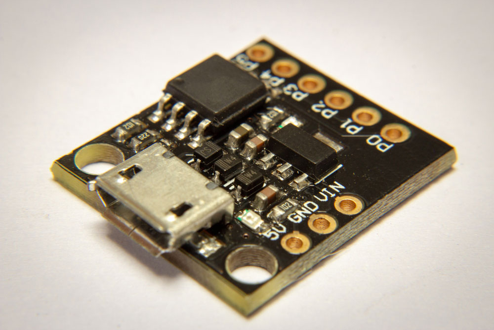
(an Arduino-like microcontroller)
What are Characteristics of Motor Drivers?
-
Compatible Motors
It is impossible to find motor drives that fit all the electric motors. Some manufacturers make motor drivers specifically for certain types of engines. However, the manufacturers make it easier for you since they provide a list of all compatible motors to motor drivers.
Notably, most drivers are compatible with the DC and stepper motor. However, a servo motor deserves more keenness when selecting a motor driver.
-
Interface
Many motor drives work perfectly when placed on an Arduino driver board interface. However, some wireless projects require a wireless motor driver. For example, the Bluetooth controller board is a good control board for a wireless project.
-
Voltage and Current
Voltage and current are the most important characteristics to look for in a perfect motor driver. When working on a project, you should already know what amount of supply voltage and operating current your project requires. The driver you intend to use should abide by the necessary level of functionality.
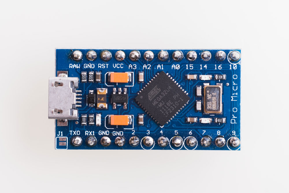
(section of an Arduino project.)
What are the Main Components of Motor Drivers?
You require the servo motor, the controller, the power supply unit, and the necessary connections for a servo motor. For the dc motor, you need a controller, motor driver circuit, DC motor, power supply unit, and the necessary direct connections.
This controller can be a microcontroller or a microprocessor. The motor driver control circuit is a current amplifier that steps up current from the microcontroller helping drive the motor.
Also, the motor causes motion. The process of interfacing the engine with the controller, brushless motor, and stepper motor often requires a motor drive controller. Moreover, the power supply unit only supplies the motor with the required current.
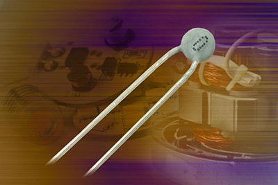
(a stepper electric motor)
What are the Different Types of Motor Drivers?
We differentiate the drivers depending on the kind of control they provide. For example, some provide non-speed control while others offer high-speed control. Notably, a single motor can use different types of drivers. However, some specific drivers work for a single-engine. The table below shows this phenomenon.
| Motor | Motor driver |
| Stepper motor | A4988, L293, DRV8833, ULN2003 |
| DC motor | A4988, L293, DRV8833 |
| Servo motor | L293 |
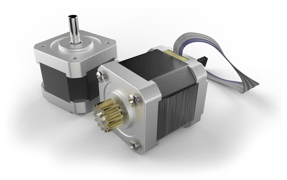
Example of a Stepper Motor Driver System: NEMA 17 Stepper Motor
One of the most popular stepper motors is the NEMA 17 stepper motor, which pairs effectively with driver ICs like the A4988 or DRV8825 for optimal performance. These drivers enable precise motion control, making NEMA 17 ideal for applications such as 3D printers, CNC machines, and robotics.
For instance:
- Motor Driver Compatibility: The A4988 and DRV8825 driver ICs are often used to control NEMA 17 stepper motors, providing smooth and accurate movement.
- Enhanced Efficiency: These drivers also help maximize the efficiency of the NEMA 17 by managing current and voltage to suit the motor’s requirements.
This combination of stepper motors and compatible drivers highlights the importance of selecting the right motor driver for your application.
(close up of a servo motor.)
Special Offer: Get $100 off your order!
Email [email protected] to get started!
How Does the Motor Driver Work?
First, the microcontroller sends signals to the motor. Then, the signs received are interpreted and stepped up in the engine afterward. The motor has two voltage input pins. Pin one turns on the driver, whereas pin 2 applies voltage to the motor via the motor IC.
If the microprocessor transmits a high input to the driver IC, the driver IC will send the same input. Consequently, this explains that the IC does not change the type of signal it receives.

(when the moves in a clockwise direction) (when the motor moves in an anticlockwise direction.)
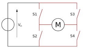
Source: Wiki Commons
For the motor to rotate clockwise, S2 and S3 switch open while switches S1 and S4 close. Then, S1 will allow its voltage to flow through the engine directly to S4. During this current flow, the circuit becomes fully complete. Further, this current will flow from point V to point M via switches S1 and S4. As a result, the motor stays on and turns clockwise.
First, we give the switches an input voltage. As a result, switches S1 and S4 will eventually close. Moreover, this forms a positive connection since we connect two parallel switches. Consequently, the motor will rotate in an anticlockwise direction. On the other hand, for an engine to turn in the anticlockwise focus, we activate the S3 and S2 switches.
(an integrated circuit.)
Why Do You Need a Motor Driver?
Notably, a driver is necessary because the microcontroller requires lower-level voltage than the motors. Due to this, we cannot supply power directly from the microcontroller to the engine. We need a motor driver in between these electrical components at this point. The driver steps up the current from the microprocessor to match the motor current.
What is an H-bridge Circuit?
Connecting two pairs of transistors in a circuit forms an "H-shaped" circuit which we call an H-bridge.
On the opposite end of the motor, place each pair of the transistors with different functionality. One team receives the input voltage, whereas the other pair remains grounded.
(an H-bridge circuit.)
Source: Wiki Commons
During a positive polarity, switch one pair of transistors at a time. Now, current flows from the source voltage to the positive terminal. Next, the current from the +VE terminal flows to the -VE terminal, which finally flows to the ground.
However, during a negative polarity, the opposite happens, and the other pair of transistors turn on. First, the current will flow straight to the negative terminal from the source voltage. Then, the current from the negative terminal flows straight to the positive terminal then finds its way to the ground.
This alternate flow of current forms an H-bridge circuit.
(photo of transistors.)
How to Build Motor Driver Circuits
What Do You Need To Build A Motor Driver Circuit?
- 9V Battery: A common power source for small electronic projects, including motor driver circuits. It provides a compact and portable power supply, delivering a stable voltage sufficient for running low-power motors and control boards like the Arduino UNO. Ideal for prototyping, it's easy to integrate into breadboard setups using a simple battery clip.
- Arduino UNO:The Arduino UNO is a microcontroller board used for prototyping and developing electronic projects. It features digital and analog input/output pins, which are essential for interfacing with motor drivers, sensors, and other components. The UNO can be programmed via USB to control motors, manage signals, and execute complex logic, making it a versatile choice for driver circuits.
- Wheels: These are mechanical components that attach to motors, enabling movement in robotics and vehicle projects. When building driver circuits, wheels are essential for translating the rotational motion of the motor into linear movement. They come in various sizes and materials, chosen based on the desired traction, speed, and load capacity for the specific application.
- DC actual motor: A DC actual motor converts electrical energy into mechanical motion, providing the driving force for wheels or other mechanical parts. In driver circuits, it is controlled by varying the voltage or using Pulse Width Modulation (PWM). DC motors are popular for their simplicity, efficiency, and ease of integration with control systems like the Arduino UNO.
- Jumper Wires: These are used to establish electrical connections between components on a breadboard or between a breadboard and other devices. They come in various lengths and colors, with male or female connectors. Essential for prototyping, jumper wires facilitate quick and flexible wiring, enabling easy modifications and troubleshooting in driver circuit setups.
- Bread Board: This is a reusable platform for constructing electronic circuits without soldering. It features interconnected rows and columns for placing components and making connections with jumper wires. Breadboards are ideal for prototyping driver circuits, allowing easy insertion and removal of components like resistors, capacitors, and integrated circuits, facilitating rapid design and testing iterations.
L293D driver is a 16-channel motor driver. It has; 4 ground pins, four input pins, four output pins, 2 enable pins, and two voltage pins.

(L293D motor driver circuit with a stepper motor.)
Source: Wiki Commons
What are the Steps to Build A Motor Driver Circuit?
To build the circuit, follow the diagram above.
- First, you safely connect the enable pins to the Arduino by the 5v pin.
- Secondly, the positive battery terminal should be by the IC while the negative terminal by the eight pins connecting to the ground(GND).
- Also, ground pins should always be shorted and fixed to the ground pin(GND) on the Arduino board.
What Are Some Applications of Motor Drivers?
Summary
A motor driver is essential to maintain the logic levels in a circuit. With the advances in technology, motors have proved to become very common.
We hope this article has been of help to you. For any queries or services on this or any of our articles, please do not hesitate to contact us.
Special Offer: Get $100 off your order!
Email [email protected] to get started!