As you may know, the potentiometer is a device for measuring voltage: low ones. It uses a simple knob to provide variable resistance. Likewise, it is what we then read as an analog input value when connecting to a microcontroller. In this case, we work with an Arduino board. Subsequently, you will learn how to set up a digital potentiometer and how to connect with Arduino. Although, there are other series of MCP41xxx digital potentiometers. For this guide, however, we shall use the MCP41010 potentiometer to create an MCP41010 Arduino circuit.
Contents
- 1. What is a potentiometer in Arduino?
- 2. MCP41010 Introduction
- MCP41010 Pin Description
- Testing MCP41010 in Arduino
- 3. How to connect a Digital Potentiometer MCP41010 to Arduino?
- Step 1: Prepare the materials you need.
- Step 2: Calculation of resistance values
- Step 3: Drawing the Circuit Diagram
- Step 4: The Arduino Code
- Step 5: Test and Simple Applications of MCP41010.
- Summary
1. What is a potentiometer in Arduino?
Also referred to as a pot-meter or pot, it is a unique resistor with three variable terminals. They comprise one wiper and two fixed-point terminals. With the aid of a microcontroller, you adjust these terminals for voltage drop variation. Generally, you control electric current flow in a circuit by resistance variation. In short, it is another controllable voltage divider.
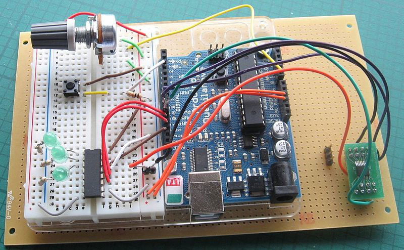
(A digital potentiometer connected with Arduino on a breadboard)
Source: https://commons.m.wikimedia.org/wiki/File:Arduino_Digital_Potentiometer.jpg
Above, we see how to connect a potentiometer to the Arduino board. In practice, potentiometers provide an effortless way to control variables. You need to write some codes that use the potentiometer values to control the LED on our Arduino board. The result is an ability to control the speed at which the LED flickers using two potentiometers. This way, you detect the state of the potentiometers by connecting them to the Arduino and a circuit.
Special Offer: Get $100 off your order!
Email [email protected] to get started!
2. MCP41010 Introduction
The MCP41010 is a digital potentiometer that comes in a tiny size, such as a microchip. Its resistance value is rated at a Max of 10 KΩ, and its Min value is 100 Ω. The MCP41010 potentiometer comprises a single channel and 256 positions.
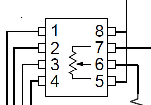
MCP41010 Pin Description
Next, you get to identify what each pin on the pot signifies. Most times, this digital potmeter usually comes in a SOIC or PDIP package of at least 8 pins.
(A description of the different pins on an MCP41010 IC.)
Source: https://commons.m.wikimedia.org/wiki/File:A-digital-potentiometer-circuit-with-a-mcp41100.png
- Terminal 1 - Chip Select = CS (This select pin on the SPI port helps execute commands after you load them in the shift register. For instance, it selects when CS Is LOW and deselects when HIGH).
- Terminal 2 - Clock = SCK ( Next is The SPI port pin. This pin, in particular, helps you clock new data into the shift register).
- Terminal 3 - Serial Data Input = SI. (Specifically, this SPI port pin inputs serial data. You write bytes of data and command with this pin into the register).
- Power Source Terminals 4/ 8= VSS/VCC. Generally, it is anywhere between 2.7 Volts and 5.5 Volts.
- Potentiometer terminal 5 = PA0.
- The Potentiometer 7 terminal = PB0. Potentiometer Wiper = PW0 (This terminal is known as the wiper. It functions to adjust resistance)
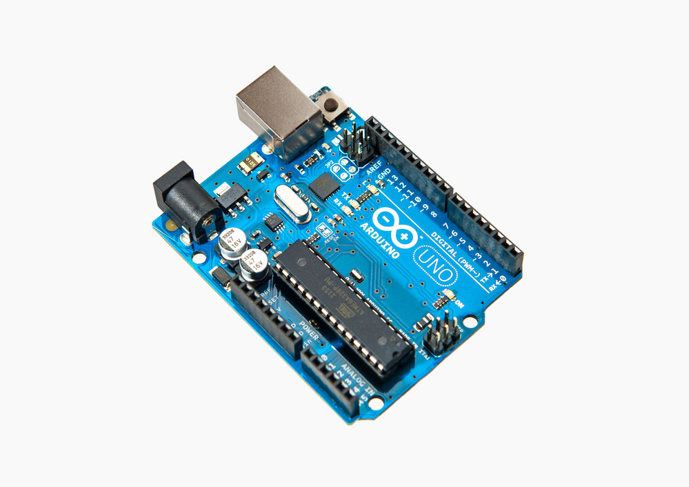
Testing MCP41010 in Arduino
The analog potentiometer and the digital ones behave alike; however, the mode of operation is different. For example, we have the manual turning of a knob in a mechanical potter. On the other hand, you control current by interfacing the digital potentiometer with an Arduino UNO.
(Stock Image of Arduino Uno)
For this purpose, connection occurs Via the SPI (Serial Peripheral Interface) port on the Arduino microcontroller. It is done so that it interfaces with the MCP41010. This SPI works as a bus for the serial synchronizing of data, which means data travels in two directions simultaneously.
For Arduino Uno and other compatible boards, there are specific SPI pins used. They include:
- Pin D10 – SS (This is not exclusive to the D10 pin. Although it is the default digital pin).
- The Pin D11 – MOSI
- Pin D12 – MISO
- Pin D13 – SCK
Now to successfully write a program in the digital potentiometer, you need to consult the datasheet. Otherwise, your first step includes sending a memory block of command (command byte) to the byte address. This command byte passes instructions to the chip, telling it what to do.
Going further, it sends a byte of data that instructs the chip on the resistance value to set. It often ranges from zero up to 255 ohms.
The next instruction is to clock commands and data bytes into the pot 16-bit shift register.
Though first, you must set the Cat first, it executes your command prompt when you raise the CS. The next step to follow is setting up your hardware.
3. How to connect a Digital Potentiometer MCP41010 to Arduino?
First, you need a set of hardware components and a program to accomplish this objective. Hence to get started, here are the few steps you need to take.
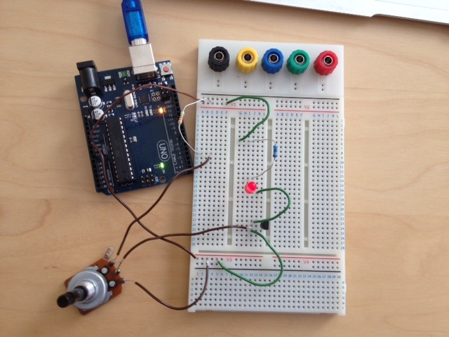
(A potentiometer connected via the pins to Arduino)
Source: https://commons.m.wikimedia.org/wiki/File:Arduino_pot_och_transistor.JPG
Step 1: Prepare the materials you need.
There are specific electronic components needed to build up the digital potentiometer connection to the Arduino. They are:
- ARDUINO.
- DIGITAL POTENTIOMETER MCP41010 IC.
- LED.
- 220 OHMS RESISTOR.
- BREADBOARD.
- CONNECTING JUMPER WIRES.
Afterward, you connect the pins correctly to the Arduino board. In effect, the IC uses the SPI protocol for communication with the Arduino Uno board.
Step 2: Calculation of resistance values
With these materials available, the next step is to calculate the resistance.
Conventionally, MCP41010 has an 8-bit sensitivity and 256 taps. With a nominal resistance of 100K ohms, it has a wiper resistance of 125 ohms.
Thus, if you need to calculate the resistance when writing 222 to the MCP41010, you'll have:
RWA = (256 - 222) * (100 * 10 ^ 3) / 256 + 125
The results in an output value of 13.41K Ohms.
Step 3: Drawing the Circuit Diagram
At this point, you're ready to design the circuit architecture. However, you'll need a suitable diagram to assemble your components and make the necessary connections.
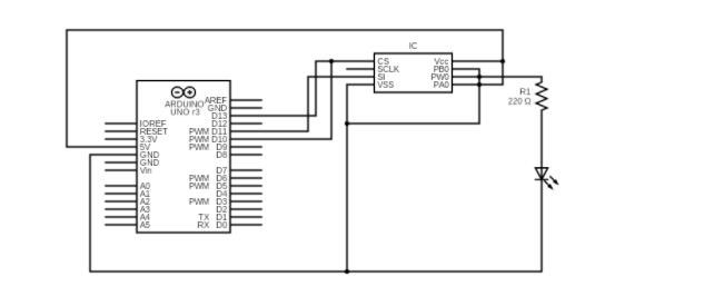
(A schematic of MCP41010 potentiometer connected to Arduino Leonardo)
Source: Wikipedia
With the sketch diagram above, designing the MCP41010 potentiometer in an Arduino Leonardo connection becomes easy.
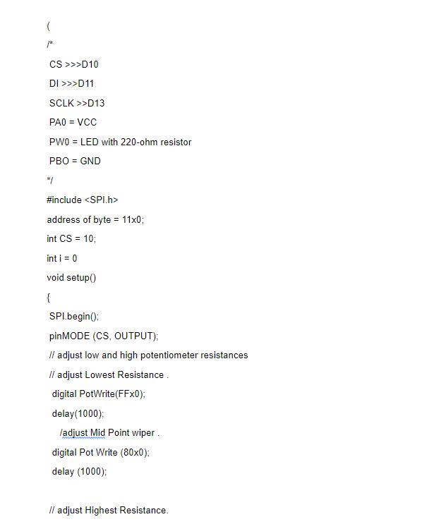
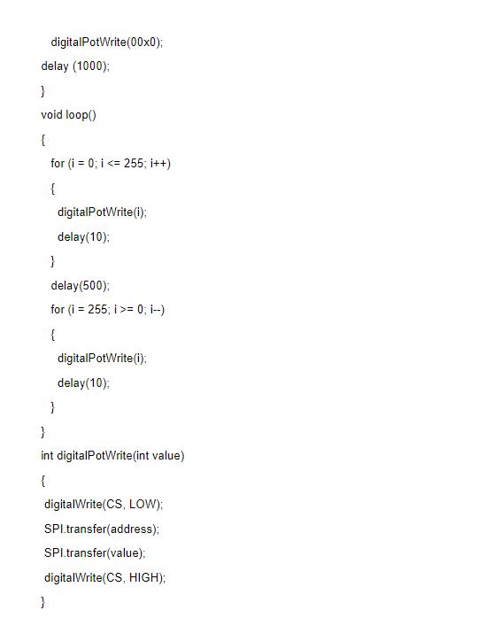
Step 4: The Arduino Code

(Procedure code abstract picture)
Next, you'll be writing a program for the digital electronic Arduino microcontroller to execute. The following code helps you control the MCP41010 interface with the Arduino software.
Step 5: Test and Simple Applications of MCP41010.
Finally, you are done coding and also now have complete control access to the digital potentiometer MCP41010. As a result, you see the MCP41010 used in diverse electronic applications. For instance,
- First is the control of the output gain of an amplifier.
- Another is in the volume control of an audio set.
- Lastly, transducer setups like microphones use MCP41010.

(Some microphones make use of the MCP41010 Arduino)
Unlike the analog version, you apply digital potentiometers to many different electronic components. For example, system calibration, offset voltage adjustment, filter tuning, sound volume control, and screen brightness adjustment.
Summary
In essence, we now know the working principle of the digital potentiometer MCP41010 in an Arduino IDE. It includes everything about setting up the digital potentiometer with a microprocessor. As a result, your potentiometer gains higher reliability and accuracy.
Overall, our services are available if you need further assistance at any stage of your electronic adventure. Feel free to contact us.
Special Offer: Get $100 off your order!
Email [email protected] to get started!