Generally, you can create a convenient and precise assembly drawing file in many ways, especially for your manufacturer. As a result, it is recommendable for designers to be aware of the information included in the PCBA drawing file.
In today's article, we will define PCB assembly drawing, then give you an outline of what you need to achieve the drawing.
Contents
What is a PCB assembly drawing?
A PCB assembly drawing displays the torque parameters for securing the screws to the casing and the exact alignment of the PCBs.
Its goal is to ensure that components have the correct installation or soldering. Furthermore, the feature is a helpful tool if an engineer has to disassemble or reassemble a product to determine a malfunction source.
Manufacturers often print the drawing design on the back of a single-sided printed circuit board (PCBs), where there's no electrical conduction.
Special Offer: Get $100 off your order!
Email [email protected] to get started!
The PCB Assembly Drawing Table of Contents
Assembly drawings and fabrications provide various information to suppliers. An assembly drawing shows how to join elements, while the PCB fabrication shows how to build a basic PCB.
At all times, start with your circuit board's design tools and the assembly drawings. Include the following general objects in both drawings.
- Drawing format
Some CAD (Computer Aided Design) systems may force you to employ a drawing format associated with a library component. But, other programs will automatically produce to use.
(CAD system in a circuit board)
When constructing your drawing, integrate the format your CAD system utilizes with your circuit board's layout, regardless of your system's approach.
-
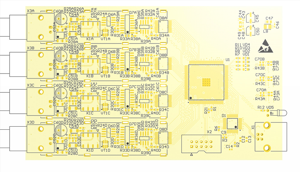
Board outline
It's the high-level schematic of your PCB extracted from the layout database. It includes cutouts and slots alongside their specified dimensions on the fabrication design. Additionally, they have references with parts on the assembly drawing.
(PCB outline from high-tech technology)
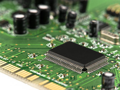
- Part shapes
Show all the component reference designators and their shapes inside the outline before soldering them onto the board.
- Mechanical parts
Also, use the appropriate hardware to show any mechanical components for board mounting.
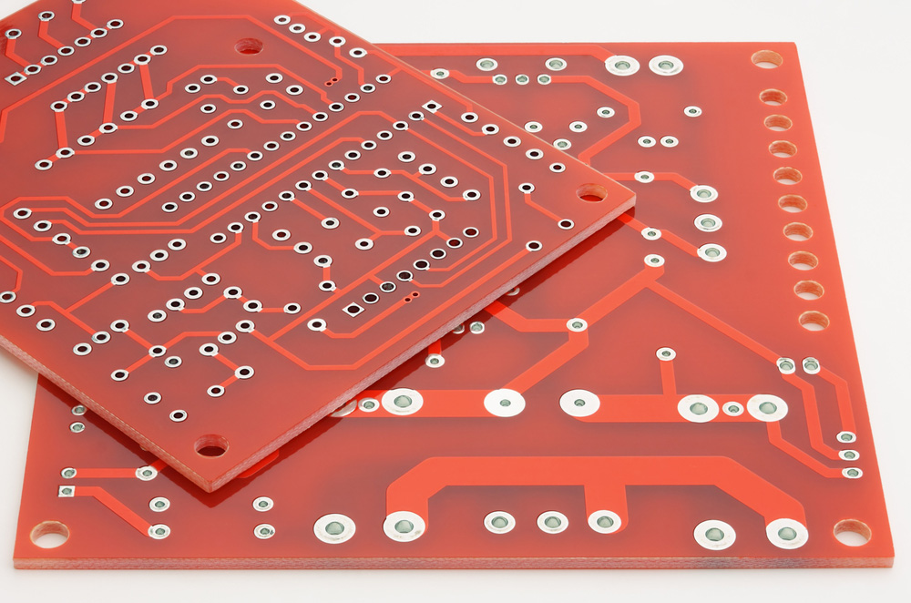
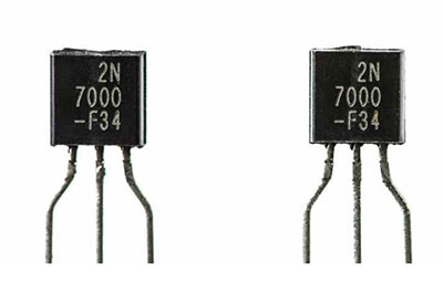
(A circuit board without electronic components)
You might need to draw the parts separately or add them manually because they lack a typical PCB footprint. We have an ejector handle that's a mechanical part. Generally, a schematic may not depict it since it is non-electrical. However, remember to include it in the bills of materials and assembly drawing.
- Assembly notes
They are the production guidelines, which contain a list of unique feature locations, industry specs and standards, and assembly details. The notes also have a components list in the package if the original manufacturer requires it.
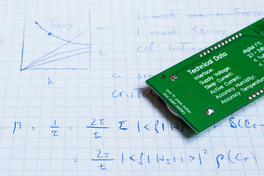
(Notes on circuit board specification)
- Identification of label locations
Any identifying labels, whether assembly tags or barcodes, use a drawing pointer for identification. Moreover, the labels might require a reference specific to them included in the assembly notes.
PCBA Drawing: Additional views
When dealing with double-sided PCBs, it's customary to have a view of both the front and reverse sides of the board. If your circuit board is compact enough, you can include both views on a single page of the assembly design.
However, you'll include extra sheets in your diagram for a larger board. You may also need to add extended views that illustrate the connection of mechanical elements on a bigger size for better understanding.
PCBA Drawing: Expanded "cut-away" views
When you need to display an assembly region (e.g., the ejector handle) in more detail, you will add a cut-away view of that section off to the side of the principal board view. The aim is to see the main board view in its entirety.
Additionally, you can scale up the cut-away view for better clarity, and you'll also need to add a drawing cursor that indicates where the cut-away view is on the main board.
PCBA Drawing: Parts list
A manufacturer may need you to directly include a bill of materials on the assembly design itself. Often, it occurs more with boards that are smaller in size.
(Components in a PCB)
Here are several basic fabrication elements of drawing to incorporate;
- Notes and Dimensions: The board's dimensions display its overall size and the placement of various components relative to and inside the board's outside boundary. Further on, the annotations provide the fabricator with essential information not covered elsewhere.
- Board Layer Stack-up; It's a board's cut-away view illustrating the construction of a PCB. Usually, board pointers describe the layout and breadth of the board's conductive layers and the core and prepreg layers connected to them.
- Drill schedule/ Hole chart: A table lists the drill symbol and number of holes required by each final hole size.
- Drill location; You must show the location of all holes you're to drill, whether for vias or components. Typically, your PCB design CAD software will automatically produce them for you.
Fabrication will rely on your NC drill file for real hole positions. The symbols for the drill bits are important for reference.
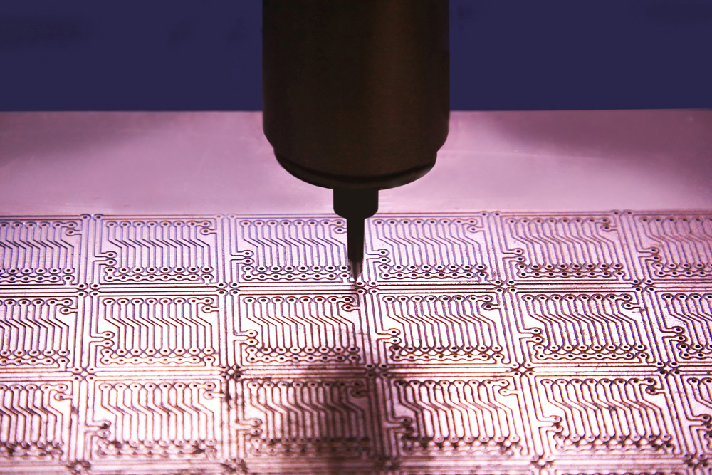
(drilling holes in a PCB)
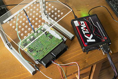
How Your PCB Design Tools Can Help
Generally, older PCB design systems lacked drawing features. As such, manufacturers needed to make the mentioned objects manually. Other times, we utilized third-party CAD drawing apps for convenience.
Fortunately, PCB design technologies today can construct whichever drawing with incredible automation. So, if you're still utilizing an outdated PCB design system that consumes a lot of effort, consider exploring today's advanced design tools.
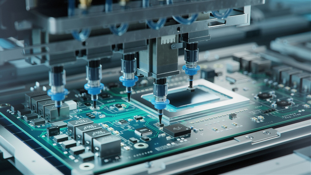
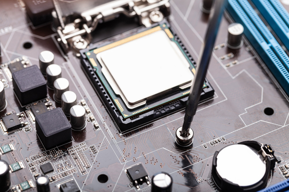
(Automatic placement of electronic components in a circuit board)
How is a PCB fab drawing different from an assembly drawing?
The purpose of a fabrication drawing is to provide specific information on the standards to meet when manufacturing a circuit board. Conversely, the schematic of the assembly drawing shows in greater depth how to fasten every single component to a circuit board.
As a result, the assembly drawing is the foundation for mounting components and programming automated device-positioning machines.
Conclusion
Suppose you want to find out more about how CAD systems, talk to our team of specialists. They will provide you with a solution that fits your needs.
Special Offer: Get $100 off your order!
Email [email protected] to get started!