There are many integrated circuits, and the IC 4093 is one of the unique types. You may mistake it for the typical NAND gate, but it has different principles of circuits. It is also a Schmitt trigger fundamentally due to its structure and functions.
Read on for a stepwise illustration of the electronic theory and applications of IC 4093.
Contents
What is an IC 4093?
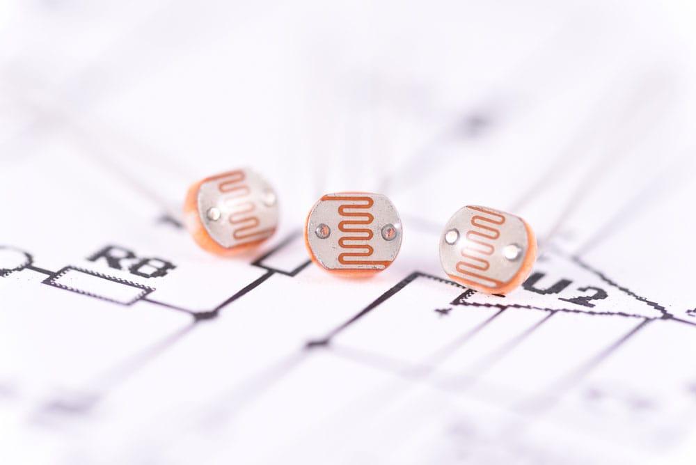
Figure 1: A photoresistor
It is a common circuit in electronic systems, but it serves a unique purpose from other circuits. You will find it in basic circuits since it is easy to configure and use.
When you look at it, you will get the impression of the typical IC. It comprises 14 pins together with four CMOS blocks which are key to its functionality. Each of the blocks is a gate. Therefore, it has two input NAND gate and gate outputs. The input current enters and leaves the electronic component via the gates.
These gates operate under basic electronics principles. For example, consider them as a circuit consisting of a single output and 2 input pins. They are similar to a transistor. However, unlike transistors which are individual components, the gates in an IC 4093 are enclosed. Thus, you may not visualize the components like in a transistor.
Also, in terms of functionality, IC 4093 gates are different from transistors. The output gates will give an output voltage that is equivalent to the specified input voltage.
So how does it operate?
The working mechanism of the IC 4093 is also simplistic.
Its primary feature is the Schmitt-trigger property at the input. Current will flow via a couple of inputs. The IC exerts a time lag on the input voltage to prevent the influence of a stray input signal. Consequently, the output signal will be proportional to the input current. Thus, you will only obtain a genuine input pulse. Also, the circuit uses a wide range of supply voltage. Thus, you can produce a high output depending on the input signal strength.
Absolute Maximum Rating
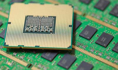
Figure 2: Several ICs
You must apply particular specifications when using IC 4093 to prevent defects in circuits. These include:
- The supply voltages must be within -0.5 to +22V.
- The input current must be within the range of +10mA to -10mA.
- The output voltage must range between -0.5V and +0.5V
- During storage, the temperatures should be between 65°C and +150°C
- For operation temperatures, use a range of -55°C to +125°C
- Each output transistor should yield a power dissipation of 100 mW
- The entire package should have a power dissipation of 200 mW
Special Offer: Get $100 off your order!
Email [email protected] to get started!
IC 4093 Features

Figure 3: A 3D illustration of a circuit board
Some of the key features of this IC include:
- It has a wide supply voltage range. Typically, you can operate between 3V to 15V.
- Each input features a Schmidt trigger. Hence, it does not require external components to activate this property. Also, it guarantees genuine input signals.
- It has a high noise immunity which goes above 50%.
- The source and sink currents are equivalent. It is because of the hysteresis voltage effects of this IC.
- The input’s rise and drop times are limitless.
- It also features a B-series output.
- It offers a guaranteed hysteresis voltage of 0.1V
How to use IC 4093?
Figure 4: 3D Explanation of Cables
The IC 4093 typically has two input pins and one output pin. For an in-depth understanding of how to use it, consider an IC 4093 with two input pins, X and Y. This truth table will give output that you will generate depending on the input signal that you apply. Thus, when you enable input, you know what to expect on output.
| Input X | Input Y | Output |
| 0 | 0 | 1 |
| 1 | 0 | 1 |
| 0 | 1 | 1 |
| 1 | 1 | 0 |
In this device, the output pin is not as critical as the gate input logic. It is useful in the external electronic circuit, but in this particular device, it has no use. Therefore, you do not risk destroying if you do not connect external components to the output.
Nonetheless, for electrical safety, do not exceed the supply voltage limit of the IC 4093 device. Ensure that you use the device within the specified range of 2V to 15V.
Aim to use undefined voltage levels of approximately between 0.75V and 2.5V at the CMOS gates. If you use a current below the 0.75V limit, you will be using logic 0. On the other hand, a current above 2.5V is a logic 1.
Thus, depending on the input signal, you can predict the output that you will obtain. You will obtain the maximum input current when you use optimal voltages.
IC 4093 Application Circuit
You will find IC 4093 circuits in digital day night switch alternating current circuits. Also, they are commonplace in street lights and even in typical direct current lighting applications. The following are some of the common AC circuits you can create using IC 4093:

Figure 5: An electrician testing a connection
-
Simple twin alternating LED flasher circuit
This circuit is one of the digital components where you will find an IC 4093. It comprises basic electronic components such as capacitors, resistors, and connecting cables. The LEDs will flash in an alternate pattern in this circuit, and you can control their flashing speed.
Note that you will increase or decrease the resistance depending on LEDs. Also, the supply voltage will determine the resistance. Therefore, to obtain the resistance, use the circuit equations:

If you are using a standard LED, you can assume the forward voltage to be 3.3V. Therefore, if you have two LEDs in series, the forward voltage is 6.6V.
-
Small Running LED Effect

Figure 6: Colored LEDs
You can also create a small running LED using simple components and an IC 4093. You will need to connect the LEDs in series. When you switch the current on, the LEDs will appear as if they are chasing each other. You can control the speed via modifying the capacitors and resistors. When you increase or decrease their numbers, the frequency of the LEDs will change.
Therefore, it is a system that you can easily control.
-
Light Activated Day Dark Switch using CMOS NAND gates and NOT gates
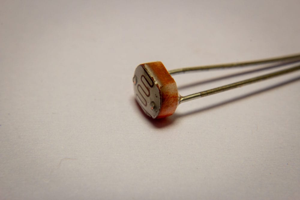
Figure 7: A photoresistor
You can use an IC 4093 in the creation of this circuit. Nonetheless, other ICs such as the IC 4049 also function similarly. The components that you need for the circuit include:
- An LDR or photoresistor with a resistance of approximately 10k to 50k in the shade
- A ceramic disc 0.1uF capacitor
- A 10k resistor
- An IC 4093
- Electronic power of 1M in preset
- A 1N4007 diode
During connection, short the control input to ensure that you convert the gates to inverters. Resultantly, you will reverse the input logic levels. A single NAND gate can be sufficient. Nonetheless, you can use three gates that will operate as buffers for a better outcome.
Conclusion
The IC 4093 is one of the most useful electronic devices, especially in lighting circuits. We have elaborated on their features and operating principles. Besides, we have laid down some of the simple circuits that you can create using this circuit.
Now you can assemble and find a use for these circuits when you follow the given guidelines. In case of a question on IC 4093 and other circuits, contact us, and we will assist you immediately.
Special Offer: Get $100 off your order!
Email [email protected] to get started!