Have you ever wondered how digital audio devices work? Or perhaps you’ve always reasoned how to send serial digital audio between chips? The answers to your questions lie with the I2S protocol.
With many technical terms and abbreviations, it’s easy to think of the I2S as a typographical mistake of the I2C version. But it’s an actual protocol and a solid one at that.
Similarly, most people confuse I2C with I2S, thus leading to some confusion about the two protocols. Luckily, we’re here to help differentiate the two.
Hence, in this article, you learn everything about the I2S protocol and how to make a digital player circuit with I2S.
Contents
- What is an I2S Interface?
- Characteristics of I2S
- Serial Data (SD)
- Word Select (WS)
- Clock
- Operation Modes of the I2S Protocol
- Right Justified Operation Mode
- Left Justified Operation Mode
- Phillips Standard
- I2S supports Arduino and Raspberry Pi
- I2S with Arduino
- I2S Interfacing Raspberry Pi
- I2S vs. I2C
- Building a Digital Music Player with I2S
- Step One
- Step Two
- Step Three
- Step Four
- Rounding Up
What is an I2S Interface?
Manufacturers needed standardized communication structures to increase system flexibility. So, NXP (formerly Philips Semiconductors) developed the Inter-IC Sound (I2S) protocol four years after the more famous I2C in the 1980s.
Today, the primary purpose of the I2S is to facilitate the development of digital audio equipment via a standardized interface.
Hence, an I2S bus will only manage the audio signal on any audio IC while transferring other signals like control and sub-coding separately. In addition, the I2S bus has only three lines which helps to limit the available pins. These lines include:
- SD (Serial data line)
- SCK (Continuous serial clock line)
- WS (Word select line)
Characteristics of I2S
The I2S interface supports three configurations: Transmitter, Receiver, and Controller configurations.
Check out the diagrams below for the configurations illustration:
The I2S drives data on the serial data (SD) line, while the WS line is similar to the audio channel (left or right) that you’re transmitting. Moreover, the last line (clock line) is responsible for carrying the serial clock.
As the diagram indicates, you can generate the WS and SCK signals with the receiver, transmitter, or third-party controller components. The component that produces the WS signals and SCK is the primary device. It’s tricky to define a controller device for a system with multiple receivers & transmitters. Thus, the I2S bus regulates digital audio data among different ICs.
Furthermore, each of the I2S’s three lines has different characteristics.
Let’s take a closer look at these characteristics.
Serial Data (SD)
On this line, the I2S transmits data as MSb first. Also, there’s no defined word length between the transmitter and receiver. However, the transmitter only sends the word length while the receiver collects what it needs.
You can also clock new data bits on the falling and rising border of the clock. But it’s crucial to clock data bits on the rising edge. Hence, the best method for clocking data bits should be clocking data out on the falling edge before clocking it on the rising edge.
However, note that I2S doesn’t include the new clock periods you usually get between words. Instead, the MSb of one word comes immediately after the LSb of the preceding word.
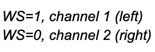
Word Select (WS)
Indeed, the select word line is the signal for channel selection. It controls the channel a transmitter selects. So, you can have two modes on this line, including logic high and logic low.
For logic lows, it indicates the word you’re transferring on WS is part of the left audio channel’s data stream. If its logic is high, then it shows right-channel audio on WS.
However, you should know this if you want to control data handling on both the receiver and transmitter end. The signal transitions of the WS should be a clock period before the protocol completes a data word.
Clock
In truth, the clock line on the I2S never stops running, and with this signal, the I2S won’t specify any maximum data rate. The clock line is also the synchronization signal an external device provides while the I2C is in slave mode. And it’s generated by a component when in master mode.
Special Offer: Get $100 off your order!
Email sales@ourpcb.net to get started!
Operation Modes of the I2S Protocol
We have three operation modes of the 12S protocol according to the location of the SD concerning WS and SCK.
They include the “Right Justified,” “Left Justified,” and “Philips Standard.”
Right Justified Operation Mode
This standard is also known as the Japanese or Sony format. In this operation mode, the left channel’s LSB is valid first at the SCK/BCLK’S rising edge before the WS’s falling edge. In contrast, the right channel’s LSB is rather valid at the SCK/BCLK’s rising edge before the rising edge of the WS.
One disadvantage of the right-justified standard is that the receiver must identify the word length of the data you want to transmit in advance.
Left Justified Operation Mode
The left-justified is different from its right-justified counterpart. Indeed, it does not suffer from one-clock delays concerning BCLK.
And both channels have MSBs valid on the primary rising border of BCLK/SCK after any changes on the WS. Therefore, unlike the right-justified operation mode, it does not need to know the word length before transmission.
Phillips Standard
In truth, the Phillips standard is a special variation of the left-justified. Interestingly, this standard changes one clock bit from the standard left-justified, causing some delays and making it different.
Here, both MSB channels are only valid on the second BLK/SCK’s rising edge after any changes on the WS.
Note: Be careful when using the I2S’s operations modes. For the Right and left Justified operation modes, we have:
The Phillips operation mode is the exact opposite of the two.
I2S supports Arduino and Raspberry Pi
You can use the I2S interface with Arduino and Raspberry Pi to build digital audio projects.
Let’s take a closer look at how this works:
I2S with Arduino
Arduino supports an “I2S library,” enabling you to program SAMD21-based Arduino boards with I2S. Using the I2S bus, you can achieve a stunted jitter audio data transmission among digital devices.
Also, you can use the I2S protocol on an Arduino to create an instantaneous MIDI audio player project. Click here for more information on the I2S library.
I2S Interfacing Raspberry Pi
If you prefer Raspberry Pi, you can also get in on the I2S action.
You can use the “4-mic array speaker” expansion board for your Raspberry Pi. Adding this expansion board to your Pi will allow you to create voice and AI applications.
Also, you can produce a more robust voice project that uses different voice services, including Google AI, Amazon’s Alexa, etc.
I2S vs. I2C
Although their names are pretty similar, they have very little in common. For example, the I2C doesn’t focus on high data rates, and it has handshaking features that allow it to function correctly in a large network of ICS.
Also, different things could go wrong in an I2C communication environment, and its complexity could affect various tasks.
In contrast, I2S has a more efficient design that moves a particular type of digital data (I2S audio). Also, it emphasizes transfer speed since you’ll be carrying out tasks like two-channel audio and real-time serialized high-resolution transmission. These tasks require higher bandwidths than what most communication tasks need.
Building a Digital Music Player with I2S
Here’s how to build a digital music player with the ESP32 and I2S:
Step One
First, find out where to connect your I2S pins. Since there are no specific pin mentions on the ESP32 datasheet, you can install your I2S on pins 15, 2, and 4 and connect your micro USB cable.
Step Two
Next, download the code for the ESP32 I2S. The code will not only set your resolution to 16 bits and sample rate to 44.1kHz, but it will also start your I2S connection. Plus, you can add a few lines to extract the data you get via a serial monitor.
Step Three
Load your code and open your serial monitor. Afterward, you should see a response in your serial monitor when you whistle into the microphone or touch it.
Step Four
Next, solder your wires to your I2S amplifier board and Micro SD cardboard. Finally, you can use the ESP8266 library to code your I2S and SPI.
After coding, connect your speaker and insert your Micro SD card with your audio file. At this point, you should hear it play.
Rounding Up
The I2S protocol can transmit digital data between DACs, ADCs, digital signal processors, filters, and other ICs that work in audio systems. Interestingly, the I2S interface’s design works for stereophonic sounds, making it a two-channel protocol.
I2S is more similar to SPI than I2C. Hence, an SPI implementation that works for unidirectional data transmission features a similar configuration to the I2C, which includes:
- one clock signal
- one data signal
- A signal for word-level synchronization
If you have any questions, feel free to reach us, and we’ll be happy to help.
Special Offer: Get $100 off your order!
Email sales@ourpcb.net to get started!