Undeniably, we often employ several electric circuits to help in signal transmission. Such devices accept and modify signals only at specific voltage ranges. Thus, higher amplitude values that surpass the range can destroy the circuit component. Also, circuit levels often tend to shift on the positive side. However, audio signals and sinusoidal signals have both negative and positive cycles, which require turning before operation. Therefore, we employ electric components such as Clamping circuits and clippers to aid in shifting signal levels and maintaining a definite circuit range.
(diode clamp circuit)
Contents
1. What is a Clamping Circuit?
A clamping circuit/ clamper is an electronic circuit in devices that fixes a signal's negative or positive peak values to a definite maximum value. It gets to the matter by shifting the DC value of the electric signal. Instead of restricting peak-to-peak signal values, a clamper moves the call in an up and down motion till the peaks reach a required reference level.
Special Offer: Get $100 off your order!
Email sales@ourpcb.net to get started!
2. How Does a Clamping Circuit Work?
In summary, a clamper circuit works as follows;
- Resistors and capacitors maintain the DC level that undergoes alteration when obtaining the output.
- Then, if you add a positive component to the input signal, you'll have your sign moving to the positive side.
- In a like manner, a harmful DC component shifts the input signal towards the opposing side.
Note the following as well;
A clamper circuit uses three components (at minimum); a diode, resistor, and capacitor. Other times, you can add a DC supply for an extra shift. The working principle of a clamper entirely depends on the capacitor's variation in time constant.
Further, capacitor C and resistor R values do affect the waveform, and you can determine their values using a time constant equation which is, t = RC. Also, ensure the values are large enough to prevent the capacitor from changing when the diode is non-conducting at certain time intervals. A recommendable time constant t = RC should be a minimum of ten times the period in an input signal voltage.
3. Types of Clamping Circuit
There are three main types of clamper circuits including; positive, negative, and biased clampers.
Positive clamping circuit
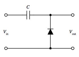
It comprises a load resistor RL, Capacitor C, voltage source Vi, and diode D.
Circuit diagram of a clamping circuit
The circuit diagram above shows that the diode has a parallel connection with the output load. And so, we'll have the positive clamper passing the input signal over to the output load with the diode in a reverse-biased state. Contrarily, it will block the input signal if the diode is in a forward-biased condition.
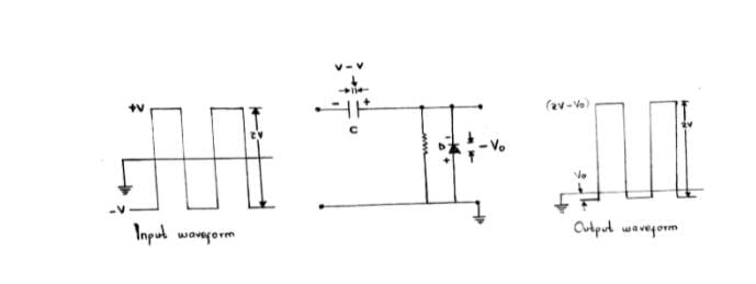
During the negative half cycle
When the input signal is in the negative half cycle, there is a forward-biased diode. Therefore, there won't be an output signal appearance. Then, the diode will allow current flow when it is in the forward-biased state. Subsequently, the current flows through the capacitor, causing it to charge to a peak value of the input voltage Vm.
The charged capacitor is in a positive/ inverse polarity with the input voltage. When the voltage levels or input current starts decreasing soon after getting to the maximum value -Vm, the capacitor will continue to hold its charge to maintain the diode at the forward biased condition.
During the positive half cycle
An output signal appears at the output in this half-cycle since the diode is at a reverse-biased state. For that reason, no current passes through the diode, hence causing the input current to flow directly towards the output waveforms.
At the beginning of a positive half cycle, the diode doesn't conduct, and the capacitor releases the charge initially stored in it. Hence, the output voltage results from a summation of input voltage (Vm) and the voltage stored in the capacitor (Vm). The two often have similar polarities.
Formula; Vo = Vm + Vm = 2Vm
The result causes an upward signal shift.
-
Negative clamper circuit
Negative clamper circuit
During the negative half cycle
The diode is in a reverse-biased state, which means a signal will appear at the output. Also, there's no electric current flowing through the diode, and therefore, the input current will directly flow towards the production.
As the cycle commences, there's a release of stored charge by the capacitor, and the diode remains non-conducting. Therefore, a summation of the input voltage (-Vm) and the voltage stored in the capacitor (-Vm) equates to the output voltage. Eventually, there will be a downward shift of the signal.
Formula; Vo = -Vm + -Vm = -2Vm
During the positive half cycle
Here, there's a forward-biased diode with no signal at the output. Therefore, the electric current will flow through the diode, then to the capacitor. Then, it'll cause the capacitor to charge up to a peak value of the input voltage but at an inverse polarity Vm. Next, a reduction in voltage or input current after getting to a maximum value (Vm) will make the capacitor hold the charge so that the diode maintains a forward-biased state.
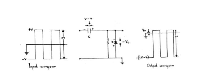
Biased clampers
Biased clampers assist by introducing an additional shift of a DC level. Also, it works the same way as an unbiased clamper, only that a DC battery has an extra DC battery.
It has further division such as;
Positive biased
It is similar to a positive, unbiased clamp, only that the output voltage offset is by the bias amount Vbias.
Formula; Vout = Vin + (VINpeak + Vbias).
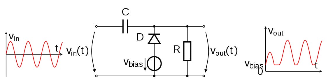
(positively biased clamper)
Negative biased
Likewise, a negatively biased voltage clamper is similar to its unbiased clamper. However, the difference is that the output voltage offset here is negative via the bias amount Vbias.
Formula; Vout = Vin - (VINpeak + Vbias).
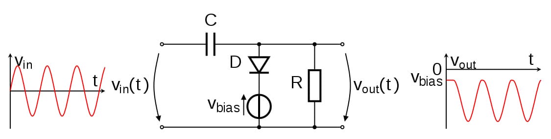
(negative biased clamp)
4. Clamping Circuit Applications
You can find clamping circuits in a wide range of applications comprising;
- As voltage multipliers or voltage doublers,
- As direct current restorers,
- In video processing equipment such as TVs,
- As test equipment such as in radar and sonar testing,

(clamp meter)
- To remove distortions in circuits,
- As base-line stabilizers, and finally
- In protecting amplifiers.
Conclusion
To summarize, the post has expansive knowledge that you need to know about clamping circuits. What's more, we have used simple terms that even a beginner can comprehend with ease. If, however, you want to discuss more on clampers, get in touch with us.
Special Offer: Get $100 off your order!
Email sales@ourpcb.net to get started!