Car circuits are more than just mechanical machines. They have several electrical systems for keeping all the various parts powered for safety, entertainment, driver assistance, etc. However, the number of circuits depends on the vehicle because the premium ones can be complex.
That said, each car has the basic electrical circuits, which you can design and fit into a PCB production. We will look at them below to help you develop them for your project.
Contents
What Are Car Circuits?
Car electrical system
A car's electrical system is a closed circuit with the battery being the independent power source. It operates on a fraction of the power running in household circuits, and the battery voltage determines the flow of current.
But the source of power is the alternator, which generates AC from the engine to charge the battery, then the battery powers everything else. There is an exception, though. Electric vehicles don't have machines. Therefore, the batteries get charged at a charging station or using the electric motors when braking (regenerative braking).
With that in mind, these are the detailed explanations of the basic car circuits.
Car Audio Amplifier Circuit
You can build a simple, low-power car audio amplifier using two TDA2003 operational amplifiers, such as the one shown in this circuit.

A car audio amplifier circuit diagram
The left and right inputs mirror each other, and the TDA2003 acts as a mono amplifier running on 12V DC from the car battery. R2 and R3 form the feedback network to set the amplifier gain, while C7 is the input decoupling capacitor. On the other hand, C4 improves the ripple rejection while C5 couples the speaker to the output coming from the amplifier.
The purpose of C1 and C2 is to filter the power supply as R1 and C3 set the high-frequency cut-off. Lastly, R4 and C6 stabilize the frequency to prevent oscillation.
The electrical circuit is easy to build and requires cheap, readily available electrical components. Also, the TDA2003 is a durable and reliable piece of hardware because it features low crossover distortion, circuit protection for all pins, low harmonic distortion, etc.
However, both integrated circuits require heat sinks for optimal operation.
Car Subwoofer Filter
While an amplifier improves the sound quality coming from the speakers, a subwoofer delivers the low frequencies in audio to ensure you get a nice bass. Building the circuit is like creating a low pass filter with a frequency adjustment range of between 60 and 160 Hz.

A car subwoofer filter circuit diagram
The primary circuit component is the TL072 dual BIFET op-amp, and you need two of them. The first op-amp acts as a buffer, taking in the left and right inputs after mixing them using the DPDT switch.
This switch provides phase control to align the subwoofer's phase with the rest of the speakers. At the second position, the DPDT induces a 180-degree phase shift. This shift delays the subwoofer's output.
R7 controls the output level while the second op-amp acts as the low-pass filter. You can alter its pass frequency by adjusting R13A and R13B. An important thing to note is that you must mount the operational amplifiers on holders.
Tachometer Circuit
A tachometer is an instrument for measuring the rotation speed, such as from engine or wheel RPM. The primary circuit responsible for this instrument is a frequency to current converter, taking in a signal frequency then transforming it into a current of proportional measure to drive the meter.
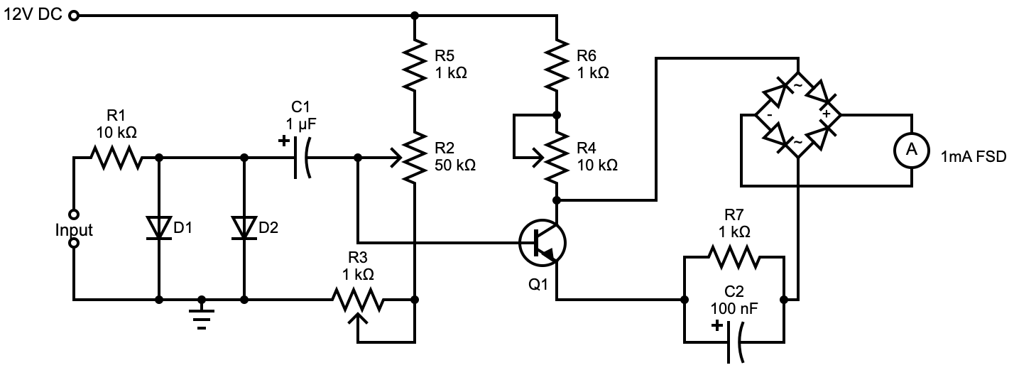
A vehicle tachometer circuit diagram
The circuit's input should be the spark plug cable, and it needs some calibration when setting up. Set R2 and R4 to 25K and 5K, respectively. After that, power on the circuit and feed a 60Hz square wave to the input terminal. Tweak R2 until the meter displays 0.36 mA, an equivalent of 3600 RPM.
Next, disconnect the input signal and tweak R3 until the meter reads 0mA. Reconnect the input signal and if the meter does not read 0.36 mA, tweak R4. After correct calibration, the meter should show 0.36 mA at 60Hz and 0 mA at 0Hz.
Once you test the circuit, take precautions when connecting the input signal. Spark plugs operate at kilovolts, so ensure the engine is off to prevent shock hazards.
Special Offer: Get $100 off your order!
Email [email protected] to get started!
Lamp Flasher Circuit
There are two ways to build a lamp flasher lighting circuit.
Using the LM317
The LM317 is a voltage regulator that can source current up to 1A, allowing you to use up to 12W light bulbs.
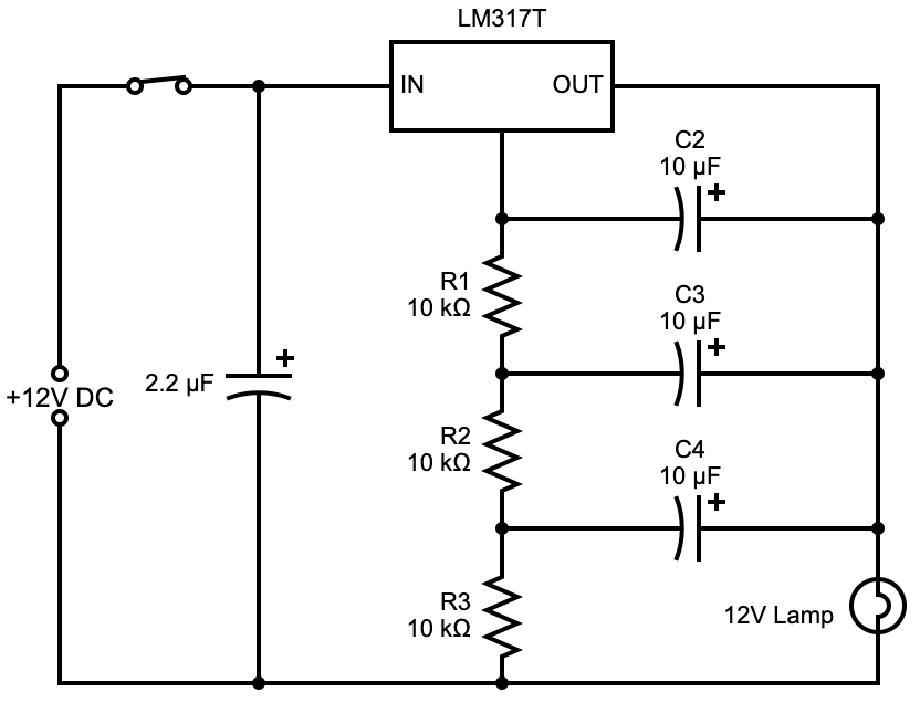
The LM317 lamp flasher circuit diagram
The flashing frequency depends on capacitors C2 to C4 and resistors R1 to R3. With the values shown in the circuit, the flasher can achieve a flashing rate five times each second.
Using the LM395
Also known as a super transistor, the LM395 is a powerful, integrated, monolithic transistor containing current limiting and thermal overload protection, among many other features. Thus, it is very durable and can switch 40V in under 500 ns while handling currents of up to 1A.

The LM395 lamp flasher circuit diagram
R1 and C1 determine the flashing frequency, and with the values given in the circuit (100 kilo-ohms and ten microfarads), the flasher can flash once each second.
Car Battery Charger
As the name suggests, this circuit is responsible for charging the car battery, allowing it can power all the other electronic circuits. It consists of a step-down transformer to lower the voltage from 230V to about 15V.

A car battery charger circuit diagram
But you need DC electrical current to charge the battery, so the output from the transformer goes through D1 and D2 for rectification. From there, the current flows through C1 for filtering and C2 for decoupling.
D3, D4, and D5 lift the ground terminal of the integrated circuit to 2.1V, which implies its output will be 14.1V (12V + 2.1V).
Diode D6 is responsible for charging the battery because it prevents the reverse flow of current from the battery back into the circuit when the mains AC power goes off. Lastly, the ammeter shows the charging current, while the voltmeter shows the charging voltage.
It is worth noting that the circuit above is for charging the battery using mains power. A car's alternator produces about 13-14V, so you don't need a step-down transformer.
Parking Sensor Circuit
Parking sensors have become vital driving aids in vehicles, and they consist of two main parts: a transmitter and a receiver.

A parking sensor's transmitter circuit diagram
In the transmitter circuit, the NE555 chip functions as an astable multivibrator. It enables D1 to emit infrared pulses at around 120Hz, and once you encounter an obstacle, the receiver circuit springs into action. D2 receives the echo signal, then IC2a amplifies it.
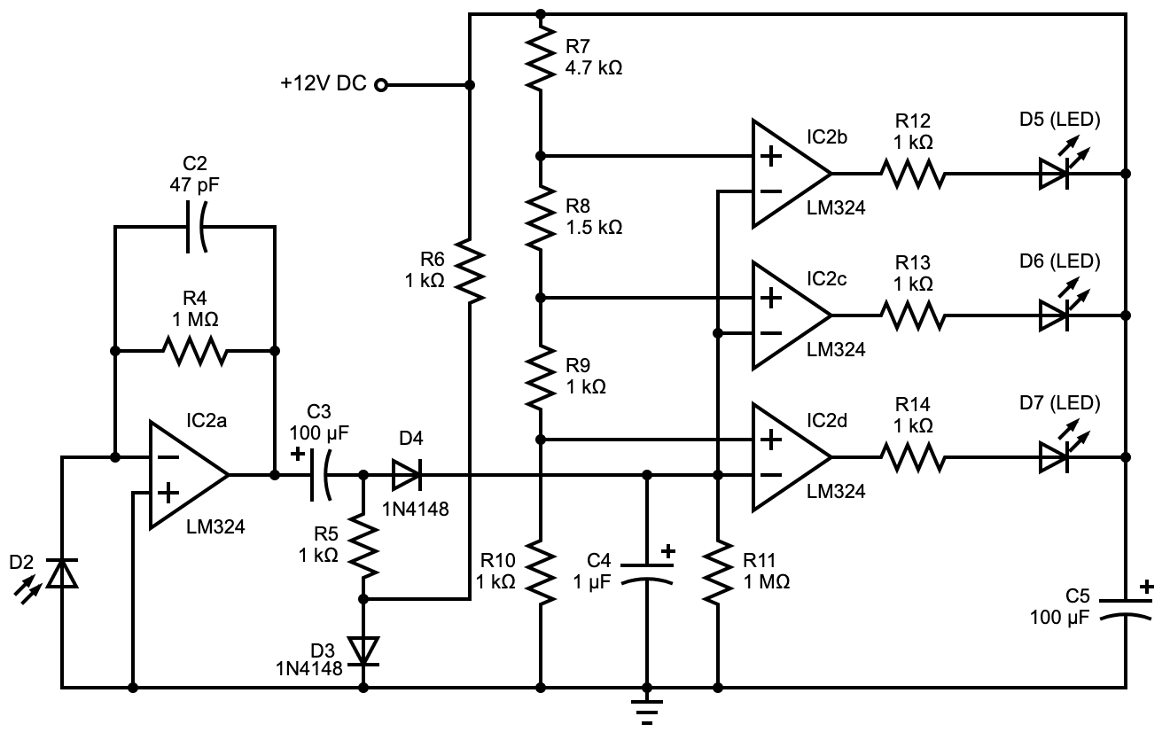
A parking sensor's receiver circuit diagram
D4 and C4 detect the amplified signal's peak, then R5 and R6 compensate for D4's forward voltage drop. On the other hand, resistors R7-R10 set the comparator's reference voltage.
The output voltage from the peak detector will be proportional to the distance between the receiver's location on the car bumper and the obstacle.
This output feeds into the inputs of the other three comparator chips. These switch the LED's status as per the input voltage of the inverting inputs and the reference voltage in the non-inverting inputs.
Therefore, the LED status indicates the distance. Beyond 25 cm, none of the LEDs will glow, but at 25 cm, D7 will light up. At 20 cm, D7 and D6 will glow, while at 5cm, all three LEDs will light up.
However, for the circuit to function correctly, the capacitor components in wiring diagrams must have a rating of 25V. Also, remember to mount the ICs on holders.
Whichever sensor type you use, make sure it detects more than just a metal body. For the IR type, place the transmitter (D1) and light sensor (D2) close to each other (2cm apart) and facing the same direction.
Automobile Turn Signal Circuit
It might look complex and complicated, but the electrical wiring diagram of an automobile turn signal is quite simple.

A vehicle's turn signal circuit diagram
The circuit consists of two integrated circuits: the TS555 CMOS timer and the CD4017 decade counter. Wire the TS555 as an astable multivibrator to trigger CD4017. Once activated, its pins 3, 2, 4, and 7 go into a high-low sequence, and the sequence speed is proportional to the triggering frequency.
Transistors Q1 to Q4 drive the connected LEDs, while the SPDT switch selects the turning direction. Therefore, you must arrange the LEDs on the corresponding side of the vehicle to match how you turn the switch using the turn signal switch.
The colors of the LEDs will depend on your preference (usually amber), but remember to mount the chips on holders.
Shock Alarm Circuit
Shock alarm circuits are vital in anti-theft systems in cars and also homes. The primary component is the piezo sensor, and its task is to detect shock to activate the system. This sensor usually sits inside the door you want to protect, which, in this case, includes all two, four, or five, close to the knob.

A car's shock alarm circuit diagram
In the circuit above, LM358 functions as an inverting Schmitt trigger. R2 sets the circuit's threshold voltage to adjust to the required sensitivity, while R1 provides feedback to the system. When the sensor is not activated, its output is low, and so is the output from the IC.
But when activated, the output voltage switches to high, which, in turn, activates the Schmitt trigger. The trigger then sounds the buzzer, producing a beeping sound that persists even after vibrations stop at the sensor and its output switches to low.
Why persist? Because increasing the inverting input has little effect after triggering the chip. It is not easy to reverse this unless you disconnect the power supply by opening the switch. This delay is vital because you want the alarm to continue beeping even after the burglar runs off.
As always, remember to mount the IC on a holder.
Summary
All these circuits require high-quality PCBs, and we are experts at manufacturing and assembling these. Therefore, if you want to build any of these circuits for your car or your project, contact us with the design, and we will deliver the complete device at an affordable price.
Special Offer: Get $100 off your order!
Email [email protected] to get started!