Get quote
Menu

0% complete

Blogs

10 Minute Timer Circuit: Amazing Facts To Know

 A 10 Minute Timer Circuit is a perfect device to choose–if you’re looking to build a circuit that works and deactivates for a set time delay.

Timer Circuit

A 10 Minute Timer Circuit is a perfect device to choose–if you're looking to build a circuit that works and deactivates for a time delay.

Mainly, we'll focus on the 10-minute timer circuit for this post. Notwithstanding, there are a ton of timer circuits that work for different purposes.So, here, we'll show you how this timer circuit works, how to make one, its applications, and much more key info.Moreover, we'll briefly discuss other minute timer circuits like 1, 5, and 15 minutes.Are you ready? Let's get to it!

10 Minute Timer Circuit

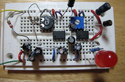
The 10-minute timer uses the 555 timer IC to operate different devices with 10-minute delays. Some of these devices include alarms, motors, and lamps. Here's the diagram of the 10-minute timer circuit.

10 Minute Timer Circuit --Components

Here are the components needed for this circuit:
  • LEDs
LEDs
  • Resistors
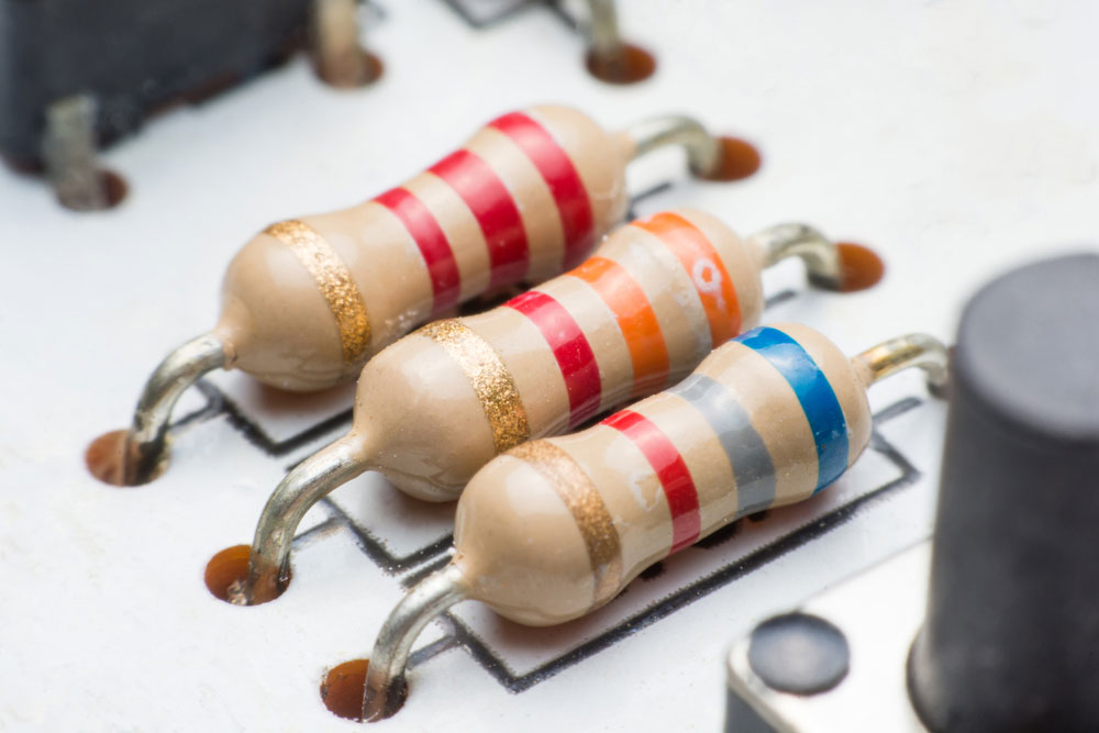
Resistors
  • Variable resistor
  • Connecting wires
Connecting wires
  • Push-button
  • Capacitors
Capacitors
  • 555 timer IC
555 timer IC
  • Power supply

10 Minute Timer Circuit --Configuration

The configuration of C2, R4, and R5 of the above circuit diagram can determine the period of a timer circuit. Thus, the greater the value of C2 with an active IC 555 timer, the longer the course stays active.Also, the total resistance value between R4 and R5 governs the maximum period the circuit stays active. So, configuring this timer for 10-minute intervals involves setting the C2 to charge for 10 minutes and changing the resistance values of R4+R5.Alternatively, you can set the resistor values only for a timer circuit to work at 10-minute intervals. Thankfully, it's not a complicated process, and you can do this with the simple formula below:T=1.1*R1*C1Now, T (time) equals 10 x 60 for this circuit since we're working with a 10-minute timer. However, the capacitor value (1000 uF) will not change. Thus, the calculation would be:T=10*60C1= 1000 uF10*60= 1.1*R1*1000 uFR1 = 545.4 k OhmMake sure you build your circuit on a PCB of good quality and be sure to mount your IC1 on an IC base. Additionally, use S1 as a push-button switch to reset the timer circuit. Here are some other tips to help in your configuration.
10 Minutes Timer Circuit Diagram Using An Adjustable Timer Circuit

10 Minutes Timer Circuit Diagram Using An Adjustable Timer Circuit

10 Minute Timer Circuit - Working of The Timer Circuit

Although the 555 timer IC works best for generating time intervals up to 15 minutes, it's not particularly useful for generating anything higher.With that said, the 555 timer IC still works perfectly for the timer circuits in this article. Generally, timer circuits work with reverse logic. Thus, an LED will stay on when the output of the 555 timer's pin 3 is low.In contrast, the LED will stay off when the output pin is high. Here's how it works.Initially, the timer sets pin 3 low and turn on the LED to indicate that it's not active. When you activate the timer with the push button, it sets pin 3 high and turns off the LED. However, pin 3 will be low again after the calculated time duration—turning on the LED to indicate the completed course.Alternatively, you can have a flexible 1-10 minute timer circuit with similar yet different working principles. Adjustable timer circuits use two LEDs (green and red) as indicators. While the green LED shows when the timer is active, the red LED shows when the timing is complete and turns on beeper sounds.Also, you can easily set the time delays of an adjustable timer circuit from 1-10 minutes by changing the values of the variable resistor.

10 Minute Timer Circuit --Other 555 Timer Projects

Though the focus of this article is on the 10-minute timer circuit, we won't neglect the other timer projects, including the 1-minute, 5-minute, and 15-minute timer circuits. Interestingly, you can create most of these projects by changing the resistor values of your timer circuits. However, to better understand how they work, let's look at these 555 timer projects.

10 Minute Timer Circuit --1-Minute Timer Circuits

1-minute timers can only turn an LED on and OFF after a minute. It can set its timer high for one minute before putting it too low afterward—creating an oscillating pulse effect.We can calculate the resistor values needed for a one-minute timer circuit using the above calculation. Here, T (time) will be 60 seconds. Thus, this timer circuit can be used for clock circuits like short and standard.T=1.1*R1*C1C1= 1000 uF 60 = 1.1*R1*1000 uF R1 = 60/ (1.1 x 1000 uF) R1 = 55kSo, setting the value of your potentiometer to 55k will set your timer for exactly one minute. We'll also use this formula to determine the resistor values for 5-minute and 15-minute timers.

10 Minute Timer Circuit --Circuit Diagram

One Minute Timer Circuit Diagram

One Minute Timer Circuit Diagram

5 Minutes Timer Circuit

Like the other timer circuits, 5-minute timer circuits turn LEDs on and off after a time delay of precisely five minutes. You can use the 5-minute timer simple circuit for applications like snoozing alarms after five minutes.Also, we'll use the same formula to determine the exact resistor values for the 5-minute timer circuit. Here, T (time) = 5*60.T=1.1*R1*C1T = 5*60C1= 1000 uF 5*60 = 1.1*R1*1000 uFR1 = 272.7 k Ohm

Circuit Diagram

Five Minutes Timer Circuit Diagram

Five Minutes Timer Circuit Diagram

15 Minutes Timer Circuit

  15-minute timer circuits work like the other timer circuits but with a time duration of fifteen minutes. These circuits work for more time-demanding applications like ringing a bell after fifteen minutes or for fifteen minutes egg cookers. For getting the resistor values, T (time) = 15*60. Here’s the full calculation: T=1.1*R1*C1T = 15*60C1= 1000 uF15*60 = 1.1*R1*1000 uFR1 = 818.2 k Ohm Thus, changing the resistor R1 to 818.2 k ohms will turn on the LED after fifteen minutes.  

Circuit Diagram

Fifteen Minutes Timer Circuit Diagram

Fifteen Minutes Timer Circuit Diagram

Applications

  Timer circuits are unique because they offer different time delays that help us automate real-life actions. Moreover, you can set these timers to perform activities you desire, even without your presence. Without further ado, here's a list of the various applications a timer circuit is valid for: 1. Timer circuits can work as lamp dimmers. So, with it, you can dim the glow of your lamp after a set time interval. 2. You can also use the timer circuit in air coolers. When the mats are wet, you can automatically deactivate the pump and activate it when the carpets dry up.3. The timing circuit is an excellent tool for producing device alarms after a set time interval.
  1. For cyclic operation, you can use a time-circuit for electronic appliances.
  2. Timer circuits are perfect for controlling the wiper speed of vehicles. You can also set the time you want the wiper to run.
Wipers

Wipers

Wrapping Up

The 10-minute timer circuit doesn't have a complex design. So, it's one of the best options for a minute timer circuit.Plus, the 555 timer IC is a significant component of any timer, and it's reliable enough to create time delays of up to twenty minutes.You don't need to design different timer circuits for various time delays. All you have to do is create a past course and then modify the value of the resistors to make your desired time delay.We hope you comprehensively know how the timer circuit works and can effectively utilize them in your applications. But, if you still have any difficulties, feel free to contact us. We'll be happy to help.

Hommer Zhao

Founder, OurPCB

Hommer Zhao, based in Shijiazhuang, China, founded OurPCB in 2007, a PCB Manufacturing company.

As a regular contributor to Circuit World and the Journal of Manufacturing Systems, Hommer shares expertise on advanced PCB fabrication processes. His research on manufacturing optimization appears in the International Journal of Production Research and Journal of Industrial Information Integration.

Serving on the Indian Printed Circuit Association (IPCA) advisory board, Hommer Zhao frequently presents at technical seminars and industry exhibitions. He maintains strong partnerships with leading institutions including UCL's Electronic Engineering Department and their PCB prototyping facilities. Under his leadership, OurPCB has pioneered enhanced PCB manufacturing machining capabilities for high-precision PCB manufacturing, particularly serving telecommunications, automotive, and medical device sectors.


Step 1 of 3

Get a free quote

What can we build for you?

Choose a service to continue to step 2
Enter a different quantity

One file, up to 100 MiB. CAD, Gerber, documents or archives.

Quotes within 24 hours · No obligation

PCB project ready?

Get a free quote