About Treadmill Motor Controller Circuit Diagram, A motor controller is an essential part of a treadmill. The controller works with DC power input to DC power output to work with the DC motor. It mainly works with an 80-260 VDC motor and can allow a treadmill user to control the belt speed.
To further understand how the series motor controller works, we have to look at its power circuitry. Therefore, keep reading for conclusive information on the treadmill motor controller circuit.
Contents
1. PWM Based Motor Speed Controller Circuit
Two 555 ICs can work together as a PWM generator to control the motor current hence work as a motor speed sensor.
The setup allows the controller to regulate the actual motor speed and work as a bidirectional motor controller.
Additionally, its controlling method enables it to use safety switches for adjusting exercise machine settings.
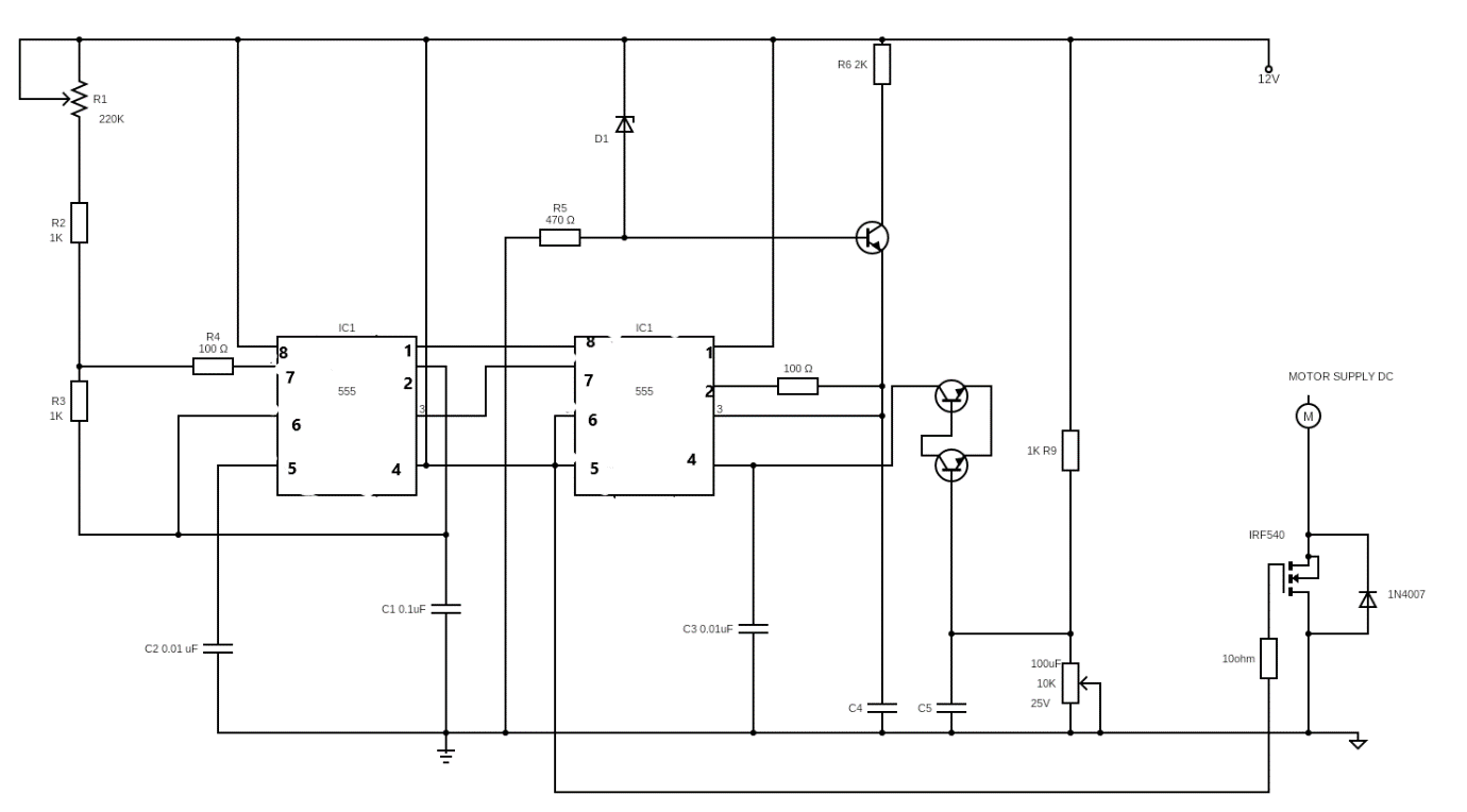
The circuit also has control of output voltage; therefore, it ensures the treadmill still consistently moves even at low speeds. Below is the schematic diagram of the treadmill motor controller.
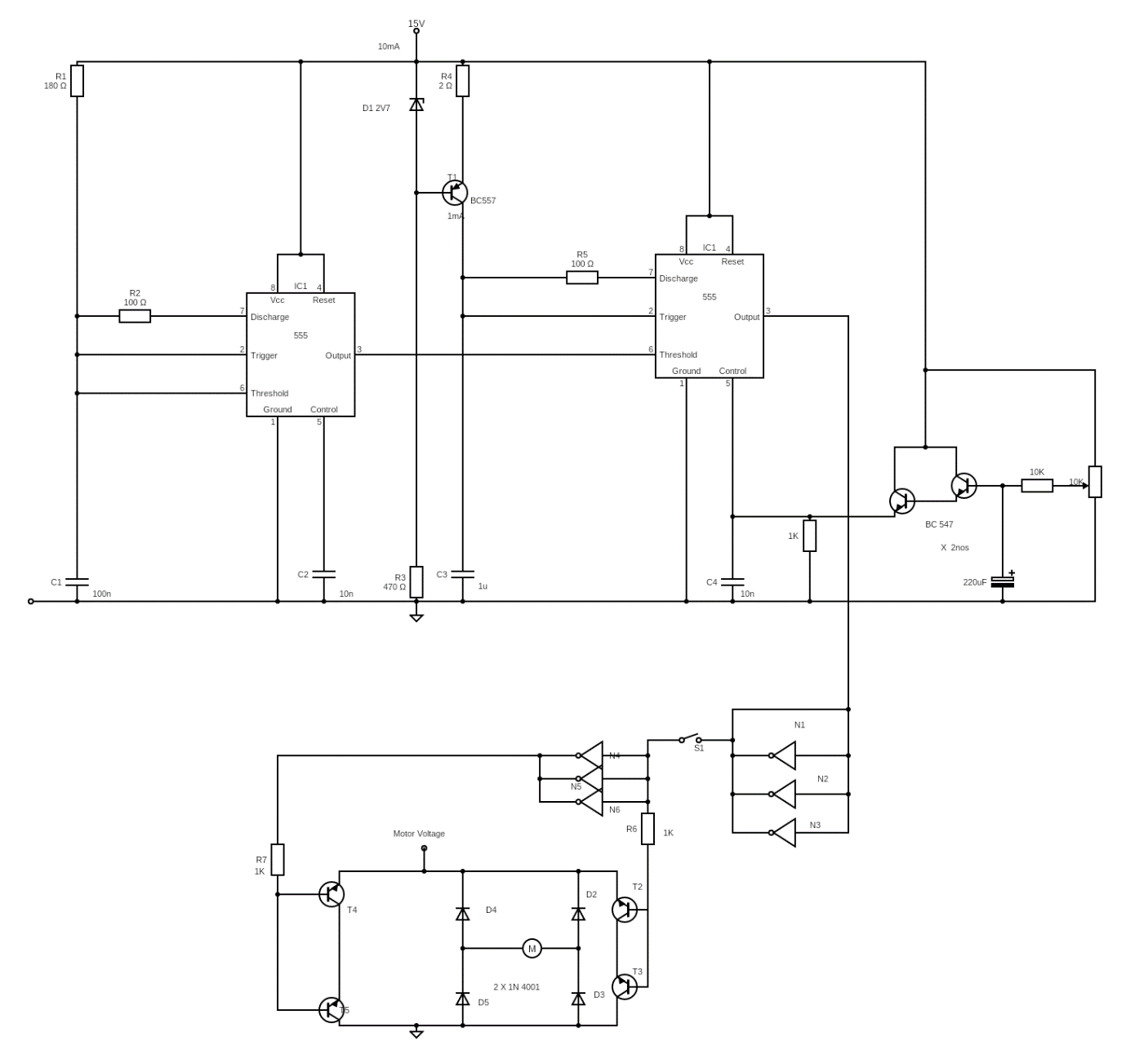
Circuit diagram for Treadmill motor controller
In the circuit, IC1 is the frequency generator of 80Hz. However, this value can vary and is not a matter of concern.
The frequency oscillates from IC1 through pin three into IC2 via pin 6. Since IC2 works as monostable in the control circuit, it also responds with an 80Hz frequency.
The response forces a similar triangle wave frequency at pins 2 and 6 of the IC2. Immediately a set potential at pin 5 of IC2 compares the frequency wave, thus chopping the input power at pin 3.
The potentiometer at pin four on IC2 creates a control signal divider network that allows power input manipulation. Therefore, working as a current detection signal to control the motor with speed variation.
The PWM control signal travels through two-phase NOT gates that are pulse inverters with the help of the SPDT switch. Therefore, the switch is essential when the treadmill user needs to change the rotation direction of the motor or stop it from rotating.
The transistors should have the same rating as the motor current in this circuit. Additionally, the power supply across the bridge should be equal to the motor's circuit board power requirements.
Additionally, here is a video with more about treadmill motor control.
Special Offer: Get $100 off your order!
Email sales@ourpcb.net to get started!
2. Simplified Treadmill Controller Circuit Design
You can use an alternate method to wire the circuit to remove the reverse forward user controls feature. It is possible by eliminating the circuit's lower control board additional components.
Therefore, the controller board circuit diagram would look like the one below.
Simplified circuit diagram for treadmill motor controller
To enable treadmill motor control, include a 1K potentiometer across pin 5 of the second IC. Also, add another to the ground wires on the same pin. Alternatively, you can add a pot parallel to C3.
Additionally, the 10K pot works as the motor speed sensor. Likewise, the 220uF is a smoothing capacitor that allows control of the motor with speed variation.
Therefore decreasing power input to the capacitor decreases the treadmill's soft start feature.
3. Controlling Through an External Power Supply
Notably, we can modify the power factor control circuit to use an external variable power supply as a control switch. It is possible by driving pin 5 of IC2 with a 0-5V power input from an unstable power supply.

Circuit diagram showing how to use an external power supply as a controller
Nevertheless, you can modify the earlier application circuit with a 1K pot at pin 5 of IC2. To clarify, that is, if you do not wish to use an external voltage supply.
Thus, the pot would allow you to adjust the treadmill's control signal. Then you can even change C4s value to include a soft start feature when switching on the motor.

Circuit diagram showing how to use a 10K pot controller for a treadmill motor
4. Using A Dimmer Phase Chopper Circuit
Commercial dimmer switches like those in home fans can also control the motor's speed. The buttons chop power output from a mains phase power source and thus allow speed control, as shown below.

Using a dimmer phase chopper circuit to control treadmill motor speed
Mainly, use a non-polar smoothing capacitor in the position between the rectifier. To specify, use 10nos of 400V parallel, thus helping the motor's non-polar capacitor filter power adequately.
Conclusion
In conclusion, we have seen how to use a couple of wires and basic transistors to modify a treadmill motor controller circuit. Hopefully, this guide helps you grasp the various working concepts of a controller board circuit. You can also contact ourPCB for any queries or clarification if you decide to try out the project.
Special Offer: Get $100 off your order!
Email sales@ourpcb.net to get started!