These days, many electronic devices and circuits use DC choppers to control the amount of power, whereas, in power electronics, engineers use them as a signal modulator. Therefore, It is essential to understand the types of dc choppers and their working principle since it will help you build the perfect fabricate PCB for your project.
Contents
What is a Chopper?
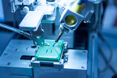
Dc-Dc Converter Circuit Board.
Source: it.wikipedia.org
In its simplest definition, a chopper is a device that converts direct current from one state to another, from a fixed constant state to a variable form. This state change is necessary for electronic circuits to control the amount of power supply a load needs. A load is the end-user of power in an electric circuit, for instance, a light bulb.
For a load to work efficiently, a chopper has to deliver the right amount of power supply. And it does this using a high frequency on and off switch for a specific period. Therefore, the amount of energy a load needs(load voltage) during a period will determine the switching frequency of the chopper.
In other words, it works using two different voltage levels and switches between them rapidly to match the desired voltage and current output.
DC Chopper: Operating Principles
There are two main types of DC choppers. These include the passive DC Chopper and active DC chopper circuit, which both have their unique differences.
The difference between a passive and active DC-chopper is as follows:
- A passive DC chopper opens up (cutting all voltage) and closes (connecting to a source voltage) a switch at a high frequency, making the output voltage waveform look like a square wave.
- An active DC chopper circuit works by maintaining an almost 50% duty cycle and uses switches controlled by amplifiers or transistors and diodes for rectification. Modern designs use this technique for efficiency and better output voltage regulation than a passive DC chopper circuit.
Special Offer: Get $100 off your order!
Email [email protected] to get started!
Applications of DC Choppers
- Switched-mode power supplies, including DC to DC converters.
- Used for speed control for DC motors
- Driving brushless DC torque motors or stepper motors in actuators
- Class D electronic amplifiers
- Battery chargers
- Electric cars

Electric Car Charging
- Railway and Subway Cars
Benefits of a DC Chopper
The main benefit of using a DC Chopper circuit is its use in many different applications in electronics. The main reason is; that they have an almost 50% duty cycle, which allows for excellent output voltage regulation.
Other advantages include:
- Has excellent efficiency and smooth control.
- Output current and voltage level stabilizer.
- The regulated output allows for a less current draw in some circuits, making them more efficient overall.
- It has high size flexibility, which makes it ideal for portable devices and minor components. Can generate RF signals.
- It is cheap and easy to maintain.
Typical Chopper Application Circuits
Choppers have three main categories distinguished depending on the voltage output.
Step Up chopper/ Boost converter
Step-up choppers act as a voltage booster, and they always produce a greater average output voltage than the input voltage. This chopper configuration mainly applies in motor operation for motor load and regenerative braking.
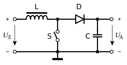
Boost Converter
Source: Wikimedia Commons.
The output voltage (V0)in a step-up chopper is greater than the input voltage (Vs). For example, an input of 6V could yield 12V out.
Step Down chopper/ Buck converter
This type of chopper circuit does the opposite of the step-up chopper, whereby the average output voltage will always be below the input voltage.
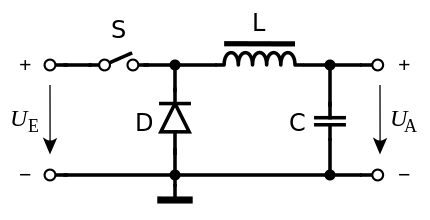
Buck converter
Source: Wikimedia Commons.
Voltage output V0 is always lower than the voltage input Vs. A buck-boost chopper (Vout = VIN x 0.5) can function differently depending on the values of Vin and Vout.
Step-up/down converters or Buck-boost converter
Buck-boost converter does both functions of a step up and a step-down chopper. Whereby it can increase or decrease average voltage output from the supply voltage.
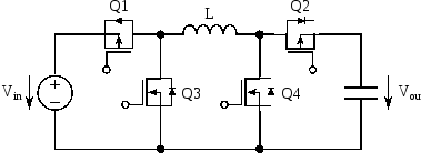
Buck-boost converter
Source: Wikimedia Commons.
The output voltage V0 in a buck-boost is always lower or higher depending on the current flow along the circuit.
Bottom Line
Chopper circuits or AC/DC converters are essential devices in making better circuits. They can regulate the output current/ voltage and reduce the current drawn from the power source.
Choppers apply in many uses such as voltage stabilization and regulation, DC to AC conversion/inverter, RF generation, and DC isolation. Moreso, they have high size flexibility, which makes them ideal for portable devices. It also allows for greater efficiency and can generate RF signals quickly. These circuits are suitable for battery charging and motor control as well.
Have some problems setting up your device project? Don't worry; you can always reach us, and we will be glad to help.
Special Offer: Get $100 off your order!
Email [email protected] to get started!