Generally, there are two types of MOSFET, N-channel MOSFET, and P-channel MOSFET, working in either enhancement or depletion mode. N-channel MOSFETs have electrons flow as charge carriers. Conversely, P-channel MOSFETs have holes as charge carriers. IRF1010E is an example of an N-channel MOSFET type. Today's post will give you a detailed guide on IRF1010E by discussing its operation, pin configuration, applications, and features.
Contents
What is IRF1010E?
IRF1010E is an N-channel power MOSFET commonly applicable in high-speed switching applications. And unlike a bipolar junction transistor, a current-controlled electric component, IRF1010E is a voltage-controlled device. It also comes with terminals on the emitter, collector, and base.
As for its operation, the IRF1010E working principle involves regulating the current and voltage between the source and drain terminals. Further, it uses a MOS capacitor, a key component in its functionality.
Pin Configuration of IRF1010E
An IRF1010E chip contains three terminals which are gate, source, and drain terminals.
Pin1 / Gate terminal; It biases the device. Often, triggering it turns on the MOSFET.
Pin2 / Drain terminal; It acts as an exit channel for electrons and has the load connected to it.
Pin3 / Source terminal: The channel allows the entry of electrons and links to the ground.
Special Offer: Get $100 off your order!
Email [email protected] to get started!
IRF1010E Features and Specifications
The main features and specifications of IRF1010E (inclusive of the ones in its MOSFET datasheet) are:
- First, you can use it in high-speed/fast switching and avalanche ratings.
- Moreover, manufacturers have developed the fifth-generation HEXFET (IRF1010E) with advanced process technology.
- The maximum operating temperature is 175°C, and its total power dissipation is 170 Watt.
- It has low turn ON resistance, therefore suitable for low-drop switching applications since there'll be low power loss.
- The maximum gate-source voltage is 20V/10V, while the maximum drain-source voltage is 60V.
- Furthermore, the maximum source-drain ON-state resistance is 0.012 Ohm.
- The maximum continuous current going through the drain pin is 81A, whereas the maximum pulsed drain current is 330A.
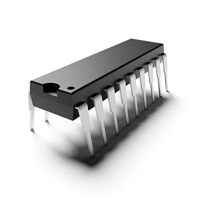
- Lastly, its package type is TO220AB.
IRF1010E Alternatives and Equivalents
The replacement solution for IRF1010E for IRF1010E include IRFB4410, IRFB4310ZG, IRFB4310Z, IRFB4115, IRFB4110G, IRFB4110, and IRF1407.
Always check on the pinout of the IRF1010E equivalent because their pin configuration might differ from the IRF1010E pinout.
How to use IRF1010E
We will use an IRF1010E MOSFET in a circuit to help illustrate how IRF1010E operates.
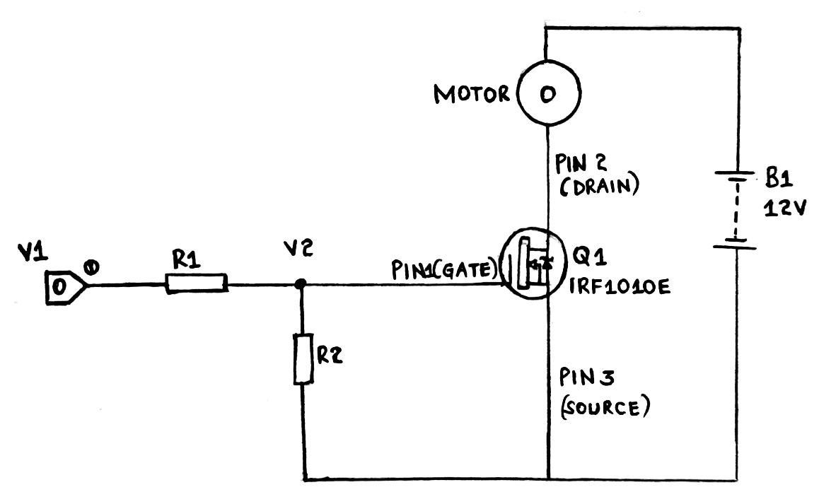
A circuit diagram using IRF1010E.
IRF1010E in the circuit above functions as a simple switching device.
- We also have the load represented by a small motor.
- Further, the control unit provides the trigger that turns ON the MOSFET. Using a microcontroller here isn't advisable because they can't produce voltages more than +5V.
- In addition, we have the source at the ground line, and the power source is from a +12V battery.
- V1 is the control unit trigger voltage, and V2 is the gate voltage.
- Resistors R2 and R1 make up a voltage divider circuit that gives a required voltage at the gate terminal. Therefore, their choice depends on the MOSFET gate threshold voltage and V1.
Let's use an example here;
For instance, we can have a control unit providing pulses +12 volts. Then, we'll need another gate voltage of 10V to help completely turn on IRF1010E MOSFET.
Therefore;
V1 = +12V
V2 = +10V
We can have R1 as 200Ω, 400Ω, or 2K pairing up with R2 that has 1KΩ, 2KΩ, or 10KΩ, respectively. Each resistor set should give an exact +10V at the MOSFET gate terminal.
The current draw from a MOSFET is negligible. Therefore, you shouldn't have that consideration when choosing a resistor set.
Circuit operation explained
- Under normal circumstances, the MOSFET circuit stays OFF because there's no Gate voltage. Consequently, a complete Vcc will appear across the OFF MOSFET. Similarly, the drain current will be zero, thus, contributing to an idle motor.
- But, if a control unit provides some voltage pulses, the circuit will gain a gate voltage. In turn, the MOSFET will switch ON and start working. Then, there will also be a drain current flowing through your motor, making it start rotating.
- If you start having a common control unit output, your gate voltage will also run low. The MOSFET will go OFF as soon as the gate voltage goes below the threshold voltage. Subsequently, the drain current becomes zero and stops flowing through the motor, preventing its rotation.
We can conclude from the above explanation that IRF1010E MOSFET is a switching device triggered by a control unit.
Note; Our circuit above represents a testing circuit. Remember to include other components like a flyback diode and heatsink if you need an application circuit.
IRF1010E Applications
You can find an IRF1010E device in the applications below:
- Relay drivers,
- PWM applications,
- Switch-mode power supply,
- Lighting systems,

(Modern stage lighting system)
- Speed control units, and
- In several switching applications.
Conclusion
To summarize, IRF1010Es is an advanced HEXFET power MOSFET in a TO-220AB package. It's a highly efficient and reliable device that greatly favors applications with high switching speeds. Remember to check the IRF1010Es datasheet before using the device in any project. If you still have questions, kindly contact us.
We are looking forward to hearing from you.
Special Offer: Get $100 off your order!
Email [email protected] to get started!