Are you looking for an affordable and easy-to-use wireless communication technology? Then, it would help if you considered Infrared or IR communication.
No doubt, the IR light looks like visible light. But it has a slightly longer wavelength. Hence, you can see the morning with your eyes, making it an ideal match for wireless communication.
For instance, the IR LED on your TV remote is responsible for the response you get from your TV. And your air conditioner remotes aren't left out as well. Also, the brain behind IR communication is the Infrared receiver circuit and infrared transmitter circuits.
How do they work? You'll get answers to this alongside the applications, benefits, and more.
Let's get to work!
Contents
Working Principle of The IR Receiver and Transmitter Circuit
Most times, the transmitter section of the IR communication has a design that helps it function in an Astable mode. Consequently, the model helps in producing a constant pulse. In addition, the pulse's frequency is 38KHz.
The light the IR LED emits is a modulated infrared light. So, if you push the tactile switch, you'll notice a close connection between the IR LED and the transmitter's output. Also, the IR LED will discharge the light at a frequency of 38KHz.
Hence, putting the infrared light close to the IR receiver will spot and extract the signal. Further, the IR receiver's output tends to be high. But when the result tracks down IR signals, it reduces.
Also, the IR receiver can turn on the transistor and lead linked to it. And this occurs because the output connects to a transistor.
Circuit Design
The whole idea behind the circuit design is to balance the infrared light that the IR LED releases. And in the design (which we'll describe later on), the TSOP 1738 is the IR receiver. As a result, it's crucial to adjust the IR signals to about 38KHz.
But you have to put it in the Astable multivibrator mode. And to achieve that, we employed the 555 Timer IC. The reason for this is to permit the 555 IC to operate as a free-running oscillator. Plus, the IC helps to produce an estimated square wave of 38KHz. Hence, connecting the IC's output to an IR LED via a button is pertinent.
As for the IR receiver circuit, the output will be low active. So, you can use the PNP transistor to make the LED come on—when the IR receiver recognizes the infrared signal.
IR Transmitter Circuit
The components you need to set up the IR transmitter include:
- Connecting wires
- NE555 Timer IC
- Power supply
- 1nF ceramic capacitor (capacitor code 102)
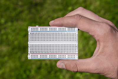
- Breadboard
- 18KΩ resistor (1/4 W)
- IR LED
- 220Ω resistor (1/4 W)
- Breadboard
- 10nF ceramic capacitor (capacitor code 103)
- 1KΩ resistor (1/4 W)
Steps
With that in mind, you can proceed to make the circuit in the following steps:
1. Reference the diagram. While at it, ensure you use the right components and connect them appropriately.
2. Focus on the transistor's base terminal. And link one infrared LED to it.
3. Get your resistor (1KΩ) and link it to the residual pins of the infrared LEDs.
4. Based on the circuit diagram, connect the LED and 220Ω resistor accordingly.
5. Use your resistors and capacitors to produce a frequency of about 38KHz. And you can calculate it with this formula: 1.44/((R1 + 2 X R2)
6. When you get to the final stage of the connection, add a power supply to your circuit. That way, you'll be able to test your IR transmitter circuit.
Circuit Working
When light reflects, the infrared light will observe it. Then, it will result in a slight current activation. When this happens, there will be a current distribution in the IR LED detector.
Consequently, it will activate the transistor—which will cause the LED switch to come on. Hence, you can use the IR transmitter circuit for projects like automatic lamps. And automatic lamps get activated when a person goes close to the light.
Special Offer: Get $100 off your order!
Email [email protected] to get started!
IR Receiver Circuit
The components you need to set up the IR receiver circuit include:
- Breadboard
- LED
- Connecting wires
- TOP 1738 (Q1)
- PNP transistor (5C558)
- 270Ω resistor (1/4 W)
- Power supply
- 10KΩ resistor (1/4 W)
Before diving into the component description, it's crucial to note that the IR receivers come in different series. And each of them has varying transmission codes that support varying modulating methods like Sony, RC6, etc.
But for the sake of this topic, we used the TSOP 1738 because it's an IR receiver for remote controls. Further, it supports the required carrier frequency for this setup (38KHz). Also, it's possible to connect the IR receiver directly to a microprocessor or microcontroller.
The TSOP 1738 stands out with its high resilience to ambient light. Also, it has low power consumption, constant data transmission, and active low power output. Plus, the TSOP 1738 is well-suited with CMOS and TTL. You'll find three pins on the TSOP 1738: OUT, GND, and VS.
The TSOP 1738 is quite convenient—considering that its package has a bandpass filter, photodetector, pre-amplifier, control, and demodulator. Asides from the TSOP 1738, your IR receiver circuit should have a microcontroller and IR transmitter.
So, the circuit diagram shows how the IR LED generates infrared light. But this light modulates at a specific frequency. Consequently, the IR receiver will get the modulated signal.
Then, the IR receiver demodulates the signal. Afterward, the call will move to the microcontroller.
Also, you won't need an additional interface due to the direct connection between the IR receiver and the microcontroller. Plus, the capacitor and resistor come in handy for suppressing any power supply disturbances.
Infrared Receiver Circuits: Pros
- It's pretty easy to build a simple circuit between the infrared receiver and transmitter pair.
- The IR receiver and IR transmitter are suitable for straightforward remote controlling applications.
- It has low power usage.
- Oxidation and corrosion don't affect the circuit.
- They have a strong resilience for noise.
- Active low power output.
- It has a solid immunity to ambient light.
- It can detect objects without contact.
- Whether there's light or not, it's possible to spot motion.
- Due to the ray direction, it doesn't experience data leakage.
- You can use it in distance measurement, security, proximity sensor applications, etc.
Infrared Receiver Circuits: Cons
- It has a small data transmission rate.
- You may not get results without a line of sight communication. That is, the IR transmitter and receiver must face each other.
- The communication is effective for only a short range.
- Things like dust, fog, etc., can affect the IR receiver and IR transmitter.
Infrared Receiver Circuits: Application
The IR receiver and IR transmitter are helpful for different sensor-related applications like:
- Temperature sensor (it helps to regulate industrial temperature)
- PIR sensor (it works effectively for an automatic door opening system)
- Speed Sensor (it allows you to synchronize the speed of different motors)
- Ultrasonic sensor (this sensor comes in handy for measuring distance)
Rounding Up
If you plan to control your devices remotely, IR communication is your best bet. And you can't have IR communication without the IR receiver circuit and IR transmitter circuit pair. Also, they are affordable, readily available, and easy to use wireless communication technology.
That said, the setup is relatively easy as long as you follow the instructions in this post. And ensure that your components are correctly connected.
Have you nailed a project using the IR receiver circuit? Or do you have questions on how to tackle your project? Please feel free to contact ourPCB.
Special Offer: Get $100 off your order!
Email [email protected] to get started!