About the button circuit, Sometimes you may need to disrupt the electrical flow in your project, allowing it to operate as intended. Now, you can easily achieve this in an electronic circuit with a push-button switch integration. Doing so ensures that the circuit completes after pressing the button. In that case, it can start or stop a machine when needed the most, even during emergencies. This makes it useful because an application will not rely on other methods to make or break a circuit.
This article will provide you with a better understanding of the push button switch. So let's take a look!
Contents
The push-button refers to a type of switch that, when pressed, completes an electronic circuit. Push buttons, which operate in high or low voltages, consist of non-conductive plastic or metallic structure. It also features two legs on each side that allow you to control two paths on a circuit through a single push. Both legs internally connect.
These input devices are set to a normally open or off state, preventing current from passing through. When you press this push button, the internal metal spring will touch two wires, causing electricity to flow.
The components, also called push switches or pushbutton switches, control a machine’s operation or process. Plus, you can find them implemented in any household or workplace setting. Some push buttons on the market come with a flat or ergonomic design. You can choose varying button switches that operate through momentary or latching action.
In addition, switches have current and voltage ratings for reliability and safety purposes. Applications with a higher current or voltage rely on expensive and large parts to operate. For this reason, push-button switches require the correct sizing. For example, cell phones and portable radios operate on small ratings. Meanwhile, industrial machines run on larger ratings.
Special Offer: Get $100 off your order!
Email [email protected] to get started!
One leg connects to the 5V battery while the other connects to LED through the resistor. At first, the push-button prevents current from flowing through the switch. However, applying force on it will complete the circuit, causing the LED to illuminate. The LED will stop glowing when you release the button since it effectively cuts off current flow from the supply.
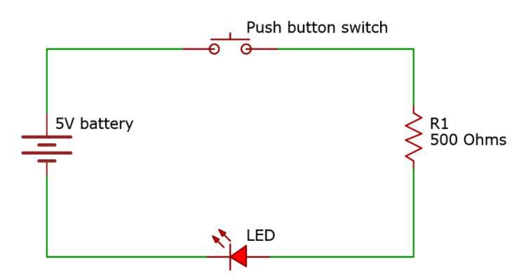 Simple circuit diagram with push-button.
Required components:
- 5V battery
- Push-button – 1x
- LED – 1x
- 500 Ohms resistor – 1x
- Jumper wires – 2x
- Breadboard
How to build the circuit:
Refer to the circuit diagram for further guidance.
First, grab a red and black connecting wire. Attach the red connecting wire to the battery’s positive terminal and black wire to the negative terminal. Afterward, connect the black wire to the breadboard’s negative power rail and the red wire to the breadboard’s positive power rail.
Next, connect one end of the push button to the battery’s positive terminal. Meanwhile, the other end connects to one end of the 500 ohms resistor. You will need to connect the other resistor’s end to the LED’s positive terminal. Lastly, connect the LED’s negative terminal to the battery’s negative terminal.
Push buttons have many different applications for various purposes in the workplace and household. In this case, they typically activate or deactivate a device. On the other hand, they can be implemented in calculators to trigger an operation.
Push-button switches can activate or deactivate a light.
- Light switches
- Shower systems
- Toilet flushes
- Arcade gaming
- Calculators
- Push-button phones
- Reset switches
- Stopping machines
Generally speaking, most buttons have a specific color, which designates their purpose. Plus, colorization helps to prevent anyone from accidentally pressing the button. For example, green indicates a startup operation, while red means that the push switch stops an action. Emergency stop buttons have a large red build, making them easier to press.
Summary
Overall, a push-button allows you to interrupt a circuit. In that case, these prove beneficial in workplace applications. You can press the button to stop a machine immediately, for example. Plus, it can interrupt the current flow, preventing electricity from reaching other components. You may also benefit from these when a project needs to perform a specific operation. So consider integrating a push-button switch next time you need to break or complete a circuit.
Do you have any questions regarding the push button? Feel free to contact us!
Special Offer: Get $100 off your order!
Email [email protected] to get started!