Overcharging is terrible for your battery health as it can cause batteries to melt or swell. It could also be damaging to users if not controlled. Additionally, the casting of the battery could become too hot and cause flammable hydrogen to build up inside the sealed battery cells, leading to a bad battery. Luckily, there is a way to prevent overcharging from damaging your batteries: battery charge indicators. So, in this article, you’ll learn everything about battery charge indicators and how to make an easy battery charge indicator circuit. Ready? Then let’s begin!
Contents
Special Offer: Get $100 off your order!
Email sales@ourpcb.net to get started!
Battery Charge Indicators
Battery indicators are devices that show the status of a battery. Plus, battery indicators usually have a visual indication that accurately displays the battery’s state of charge.
Also, different technologies that require an ideal battery to operate always have an inbuilt battery indicator. Examples of such technology are mobile phones and computers.
Some mobile phone battery charge indicators are usually in bar graphs--which means the more bars you see, the better the battery charge status. Others indicate battery charge level through percentages.
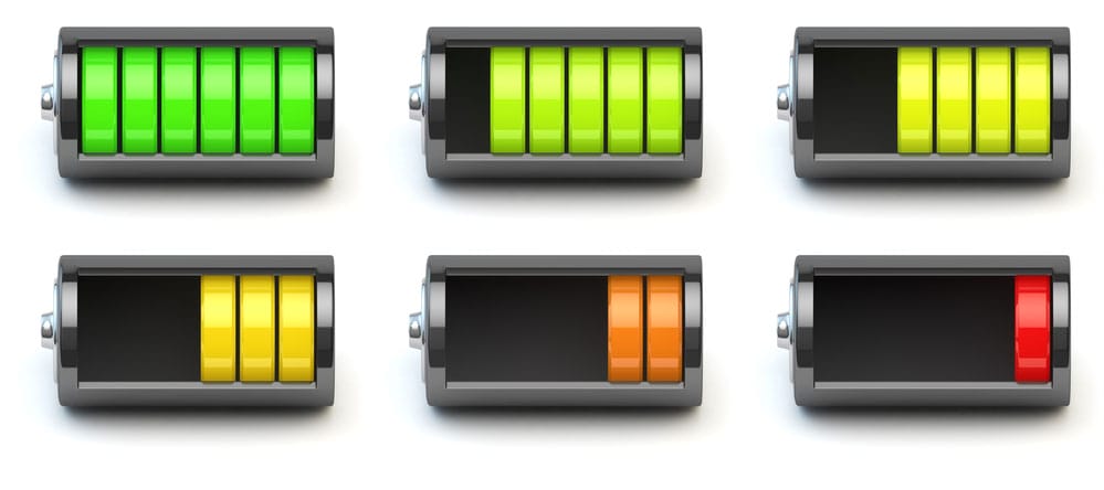
Bar Graphs
Likewise, a battery charge display shows the battery in charge mode in portable computers that use rechargeable batteries. Also, you can see the amount of time and battery power you have left when your laptop is not charging.
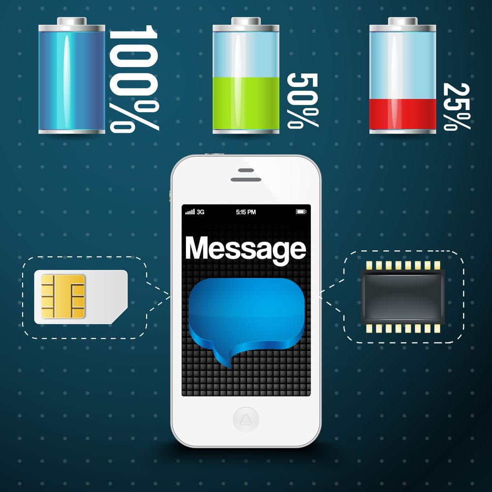
Battery Percentage
Additionally, phones and computers aren’t the only devices with a battery charge indicator. Other electronic devices like power banks and smartwatches also have battery charge indicator lights that tell you when your battery is low or full.
Furthermore, a smart battery system features a controller that’s integrated with an interchangeable battery pack. This integration is capable of delivering a more accurate indication of the battery charge state.
How to Make a Battery Charge Indicator Circuit?
There are various ways to make a battery charge indicator circuit that accurately shows the charge state. Some of the battery charge indicator circuits we’ll be discussing include a battery percentage indicator circuit, battery level indicator circuit using LM3914, and battery full charge indicator circuit employing two transistors.
Battery Percentage Indicator Circuit
This circuit is easy to show the current percentage of any battery. What’s more, the circuit is not expensive to build. Here’s the circuit diagram below:
Battery Voltage Indicator Circuit Diagram
Source: Wikimedia Commons
Components Required
- Here are the materials you need for this circuit:
- PCB (1)
- 1k Resistor (5)
- DC power supply--15V maximum (1)
- 3V LED (5)
- Few connecting wires (brown, black)
- 15k Resistors
- 10k Resistors
- 47k Resistors
Steps
Here are the steps you’ll need to follow for this circuit:
Step 1: Insert your Components
Using the circuit diagram above, insert all your LEDs and resistors into the PCB. Ensure you connect the LEDs in series.
Step 2: Solder all Wires
After connecting all your components, solder the wires of the LED and the resistors as in the image below:

Soldering Wires to Circuit Board
Source: Wikimedia Commons
Step 3: Solder your Input Wire
Next, take your input wires, brown (positive terminal) and black wire (negative), and solder them to the PCB. These wires are for the DC power supply.
Step 4: Test your Circuit
Finally, make sure your circuit matches the diagram and supply some power to the circuit. Once you give above 13v, all the LEDs on the circuit should light up.
How it Works
This indicator circuit displays the battery percentage via the LEDs in ascending order. The first LED shows 20%, while the second shows 60%. Also, the third, fourth, fifth LEDs show 60%, 80%, and 100%, respectively.
Also, different voltages will make the LEDs glow. When you supply 5v, two LEDs would glow, give 10v, and 3 LEDs would light up. Lastly, supply 13v and above, and all LEDs would glow.
Battery Level Indicator Circuit using LM3914
The main component of this circuit is the LM3914 IC, which can take input analog voltage and drive ten LEDs in a linear order depending on the voltage of the input analog.
Here’s the best part.
For this circuit, you won’t need to connect resistors in series with the LEDs. Why? Well, the IC is capable of regulating current on its own. Check out the circuit diagram below:
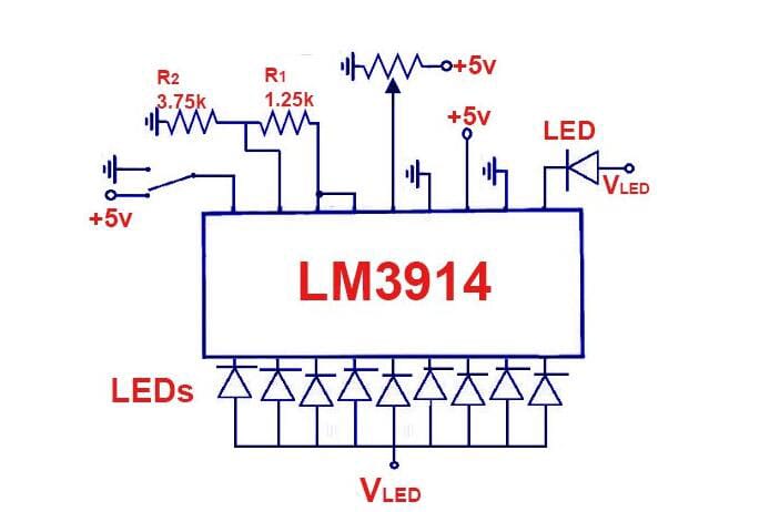
Battery Indicator With LM3914 Circuit Diagram
Components Required
For this circuit, you’ll need the following materials:
- LM3914 IC (1)
- SPST switch (1)
- Battery (1)
- LEDs (10) - (3 red, 4 yellow, and 3 green)
- Resistors (2) - (3.75KΩ and 1.25KΩ)
- Few connecting wires
Circuit Design
The LEDs (D1 to D10) show the battery’s capacity in display or dot mode. You can select your preferred mode via the SW1 (external switch), which you should connect to pin 9 of the IC.
Battery LED Status
Also, connect pin 6 and 7 to the ground via a resistor. For this reason, the resistor will control how bright the LEDs will be. Additionally, resistor (R2) and POT RV1 will form a potential divider circuit. Here, the POT RV1 will handle calibration, so an external power supply isn’t required.
Furthermore, you can use different LED colors to show the battery status. So, connect the red LEDs (D1 - D3) to show when you have a low battery. Then, connect the green LEDs (D8 - D10) to show when the battery is 80% or fully charged. While the yellow LEDs will indicate the other power status. Thus, each LED in this circuit shows a 10% battery level.
How to Test and Use
First, connect the 12v battery to the circuit’s input and adjust the POT RV1 until D1 starts emitting light.
Next, gradually increase the DC voltage input and watch the LEDs glow. The first LED will shine at 1.2v, while the second will glow at 2.4v. When you reach 12v, all 10 LEDs will light.
However, this circuit only works for small voltages and might need a few tweaks to work correctly.
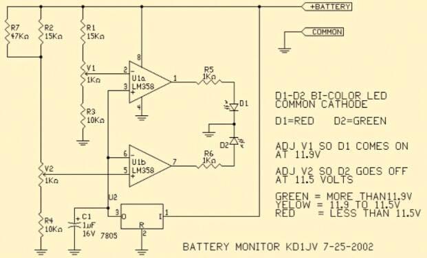
Battery Full Charge Indicator Circuit using Two Transistors
Here’s an indicator circuit with a mini design that indicates when a battery charge is complete by lighting up an LED. Also, this circuit uses only two transistors as its major components. Take a look at the circuit diagram below:
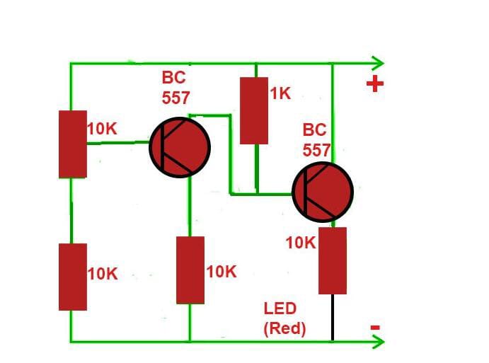
LED Switching On Circuit Diagram
Now, we’ll discuss the two presets of this circuit, so you can design your desired preset.
LED Switching On at Full Charge
This preset allows the circuit diagram above and will light up the LED once the connected battery is complete. So, to set up this circuit, you’ll have to supply the upper charge level you want and make adjustments to enable the LED to glow when it reaches the set level.
LED Switching Off at Full Charge
On the other hand, this circuit allows you to turn off the LED whenever the battery charging is complete. Here’s the circuit diagram below:
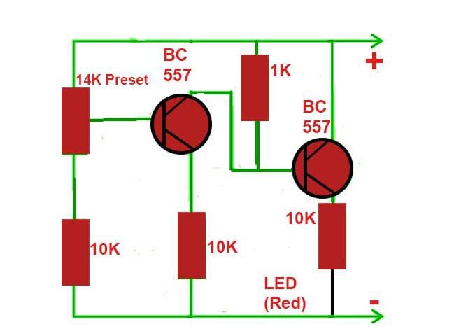
LED Switching Off Circuit Diagram
How to Set Up and Use
Setting up the above circuit is relatively easy. Like the power-on circuit, you’ll have to supply the voltage equal to the high charge level you want for the battery and then carefully tweak the circuit with a screwdriver to ensure the LED goes off at the level you want.
So, if your circuit monitors a 12v battery over a 14.3v charge level, you can tweak the preset to shut down the LED around 14v.
Rounding Up

Battery Level Indicators
Battery level indicators are essential devices for all battery-powered devices. Without it, you won’t know when your batteries need charging or stop charging when full to prevent damages from overcharging.
It’s even more critical for battery electric vehicles as the health of car batteries are crucial. Most of these vehicles come with a battery condition meter (voltmeter) that helps you monitor the condition of your starter battery.
Now, most modern cars come with ammeters that show when the battery is charging or discharging. However, both the voltmeter and ammeter can show the state and charging system of an automobile or automotive battery.
Well, that wraps up this article. If you have more questions, feel free to contact us, and we’ll be happy to help.
Special Offer: Get $100 off your order!
Email sales@ourpcb.net to get started!