About Transistor Pinouts, An electric circuit is a combination of different electrical devices. One of these electrical devices is the transistor.
A transistor is an essential part of an electric circuit. Its function is to convert a weak signal from a low resistance circuit to a high resistance circuit. Pinouts are components of the transistor, and this article seeks to discuss how they help the transistor perform its function.
Contents
- Definition of Transistor Pinouts
- Identification of Transistor Pins
- Bipolar Junction Transistor (BJT)
- Field Effect Transistor (FET)
- Metal Oxide Semiconductor Field Effect Transistor (MOSFET)
- Transistor Pinouts--Insulated Gate Bipolar Transistor- IGBT
- Transistor Pinouts--Phototransistor
- Transistor Pinouts--Connecting a Transistor to a Circuit
- Summary
Definition of Transistor Pinouts
The transistor is made up of three components. And they include the Base, Collector, and Emitter. These three components are the transistor pinout, and the Emitter is the first pinout and is responsible for the output from the transistor.
Up next is the Base, which is the central component of the transistor. And the Base is responsible for controlling the value and also receives the supply connection. The last part is the Collector. It is the biggest component of the transistor. As a result of its size, it has the largest number of carriers in the transistor.
Special Offer: Get $100 off your order!
Email sales@ourpcb.net to get started!
Identification of Transistor Pins
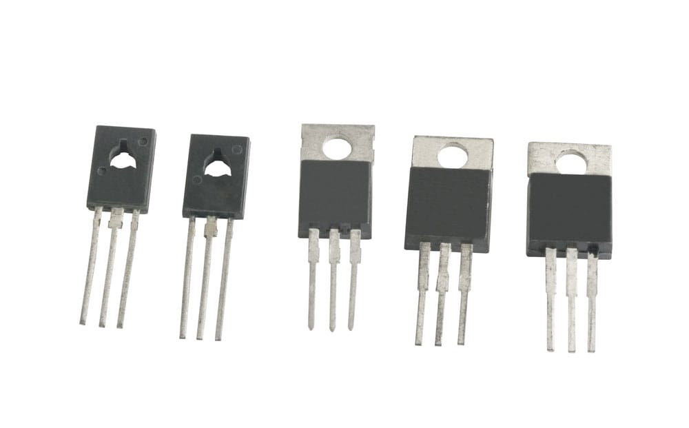
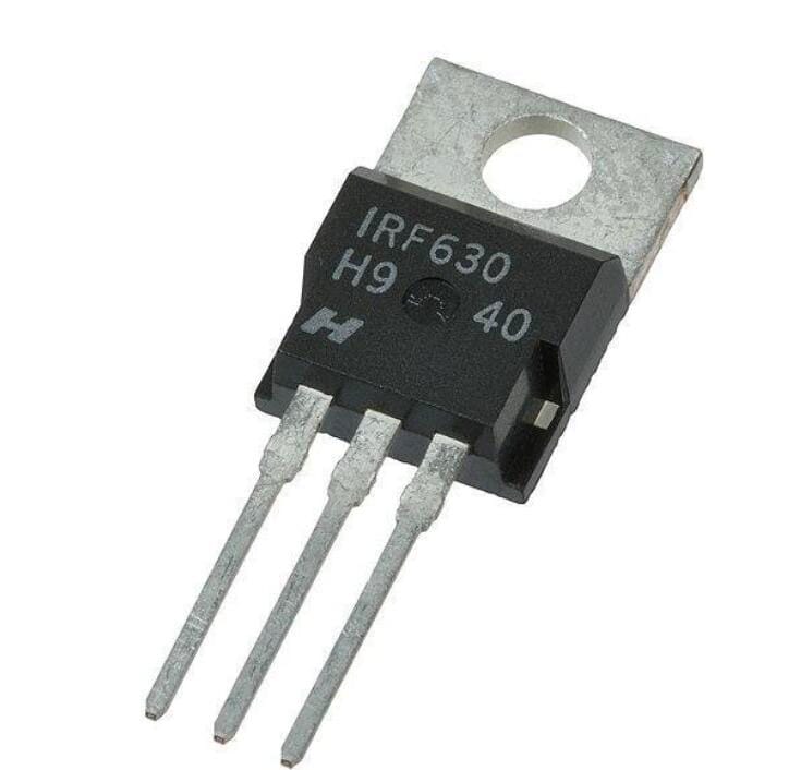
Power transistors
An example of the most common problems that professionals face while designing a circuit is identifying pin connections in many devices. These devices include transistors, TRIAC, SCR, and many other devices. Many technicians have to rely on sources such as datasheets to find the right pin connections and perfect the connection in the circuit.
This section focuses on the guide in identifying transistor pins;
Bipolar Junction Transistor (BJT)
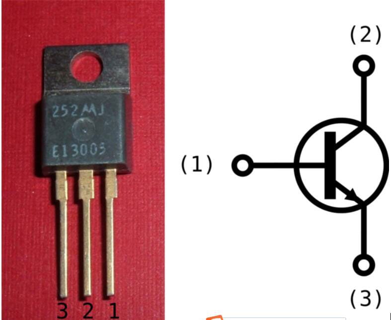
Transistors are usually of two types, NPN or PNP. These two types of transistors are generally available in either plastic or metal casing. With the plastic case, the transistor has a flat front side, and the arrangement of the pins is serial. When identifying the pins, let the flat side face you and start counting the pins.
More often than not, with NPN Transistors, the first pin is the Collector, the second pin is the Base, and the third pin is the Emitter. Thus the configuration is CBE.
Bipolar Joint Transistor
However, with PNP transistors, the opposite is the case. The first pin is the Emitter, the second pin is the Base, and the last pin is the Collector.
When the transistor uses a metal casing, the pins’ arrangement is circular. To identify the pins in this situation, locate a tab on the rim of the transistor. For NPN transistors, the closest pin to the tab is the Emitter. The pin opposite the Emitter is the Collector, while the one in the middle is the Base.
With the PNP transistor, the reverse is the case. The pin closest to the tab is the Collector, and the one opposite it is the Emitter, and the pin in the middle is the Base.
Note: There could be changes in some cases. However, in most cases, this is the configuration that you will find.
Field Effect Transistor (FET)
Field Effect Transistor
The Field Effect Transistor usually has a curved side. While trying to identify the pins, ensure that the curved side faces you. Then, start counting the pins in the opposite direction. The first pin counts as the source, the next one is the Gate, while the last is the drain.
Metal Oxide Semiconductor Field Effect Transistor (MOSFET)
Just like the Field Effect Transistor, the MOSFET uses the G, D, and S arrangement, which stands for Gate, Drain, and Source. To identify the pins in MOSFET, ensure that the front side is facing you, start counting the pins from the left-hand side to the right-hand side. You will find that the pins’ arrangement is Source, Drain, and Gate.
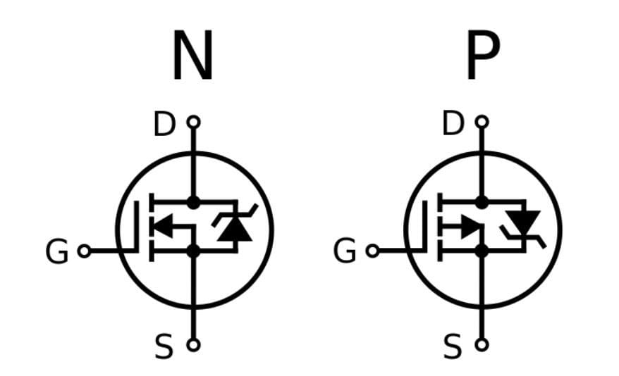
Metal Oxide Field Effect Transistor
However, this arrangement is also not sacrosanct, so it is advisable to consult the MOSFET datasheet to confirm the identification.
Transistor Pinouts--Insulated Gate Bipolar Transistor- IGBT
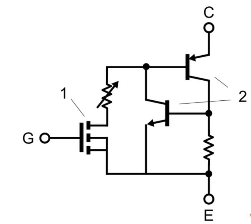
Insulated Gate Bipolar Transistor
To identify the pins on this type of transistor, you need to get a practical IGBT like the GN2470. Now, you need to hold the raised part towards yourself. In this position, the cathode is the middle one, which is usually shorter. The pin on the right is the Emitter, and on the left-hand side is the Gate.
Transistor Pinouts--Phototransistor
With a practical phototransistor like L14G2, you need to hold the transistor by letting the surface with curvature face you and start counting. The first pin from this direction is the Collector, the second is the Emitter, and the last is the Base.
Transistor Pinouts--Connecting a Transistor to a Circuit
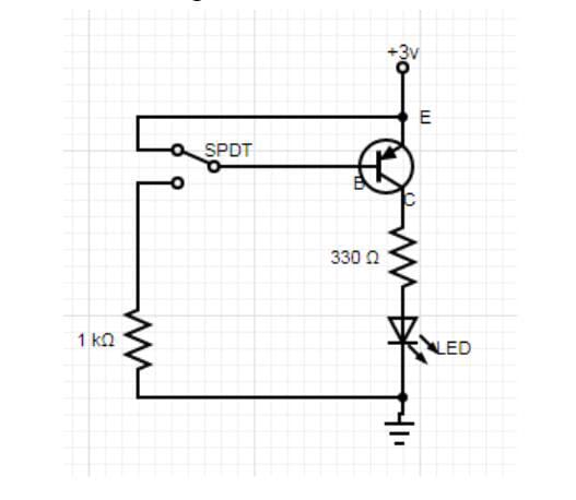
A Circuit diagram including Transistor
Regardless of the type of transistor, the method of connection is the same. The components needed for the connection include a 2N3906 Transistor, a 330-ohm Resistor, LED, Open Switch, and Dual DC Power Supply or 5 AA batteries.
The connection starts from the Emitter, with the +3V connection. You then connect the open switch to the Base of the transistor and connect the LED to the base of the transistor. The open switch controls the transistor, which in turn controls the LED.
Summary
Identifying the pins in a transistor is a simple process. However, the process involved is different for each type of transistor setup. For more questions, check out ourPCB website.
Special Offer: Get $100 off your order!
Email sales@ourpcb.net to get started!