Do you have an electronic circuit project that requires communication between devices? The MCP2515 CAN module provides the solution for your needs! It generally features useful component integrations that aim to transmit and receive messages in bytes. Of course, this makes it ideal for automotive and many other relevant applications. Also, this device offers excellent speed performance, achieved through two CAN Bus module connections.
After reading this article, you will learn more about the MCP2515’s features and capabilities. So let’s take a look!
Contents
What is MCP2515?
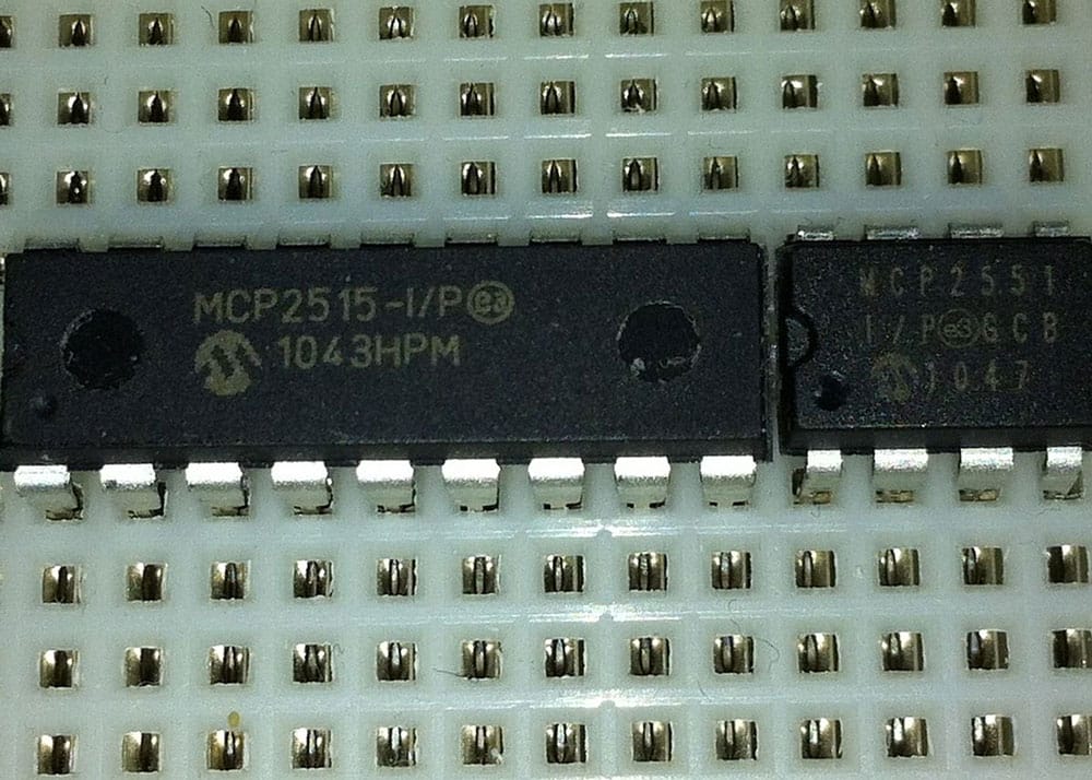
Image showing the MCP2515 IC.
Source: Wikimedia Commons
The MCP2515 device refers to a CAN (Controller Area Network) compatibility with CAN protocol 2.0B. Generally, it provides standard and extended message transmissions. It also comes with two acceptance masks and six acceptance filters to block unwanted messages.
MCP2515 CAN Bus Controller Module Features
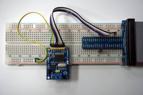
An example image of an MCP2515 CAN Bus interface connection. Source: Aptofun
Overall, the MCP2515 CAN Bus module supports 1MB/S communication transmissions, which require double CAN bus modules. In addition, this module features the TJA1050 IC high-speed CAN transceiver, MCP2515 CAN controller IC and an 8MHZ crystal oscillator. The MCP2515 IC allows a microcontroller to communicate through its SPI interface.
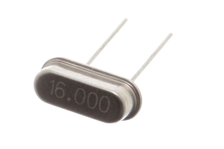
The MCP2515 module features a crystal oscillator.
Source: Wikimedia Commons
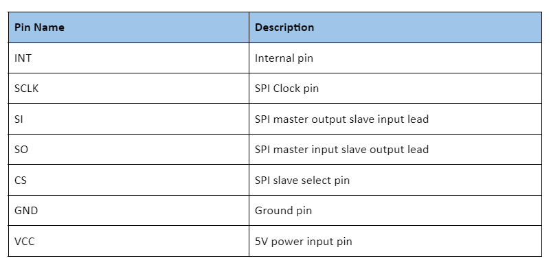
MCP2515 Module Pinout
Special Offer: Get $100 off your order!
Email sales@ourpcb.net to get started!
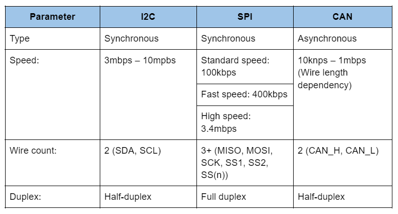
Comparison of CAN over SPI & I2C
The table below shows the speed, wire count, and duplex differences between CAN, SPI, and I2C.
Arduino MCP2515 CAN Bus Interface Tutorial
This project involves interfacing the MCP2515 CAN Controller Module with Arduino. Afterward, you will utilize the CAN Protocol and both MCP2515 CAN Controllers to provide communication between the devices.
Circuit diagram
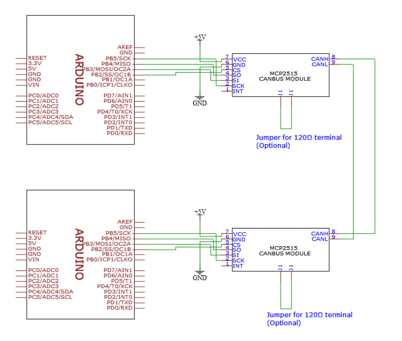 MCP2515 circuit diagram for this project.
Required components
You will need the following components for this project:
- MCP2515 CAN Bus Interface – 2x
- Arduino UNO – 2x
- USB cable – 2x
- Wires
Steps
As you know, the CAN Controller IC ensures that the SPI enables microcontroller communication. Therefore, you will need to connect the MCP2515 module SPI pin (SCK, MOSI (SI), MISO (SO), and CS) to the Arduino SPI pins. Refer to the circuit diagram for assistance.
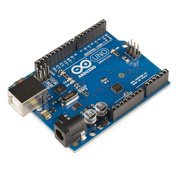
This image shows the Arduino UNO for the circuit project.
Source: Wikimedia Commons
Afterward, create two pairs of connections, operating as the transmitter and receiver. Next, connect one cable to each CANH pin on both modules. Then, click the other cable to each CANL pin on both modules. It will provide the transmitter and receiver with communication capabilities.
Code
Ensure that you download and extract the required library for this module before working on the code. After downloading the library, drag it to the Arduino’s libraries directory. Next, the communication will require a transmitter element and receiver element. Use the below code for the transmitter and receiver.
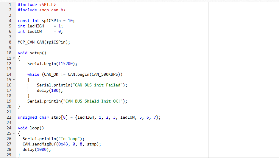
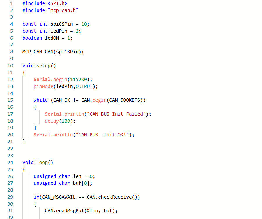
Transmitter Code
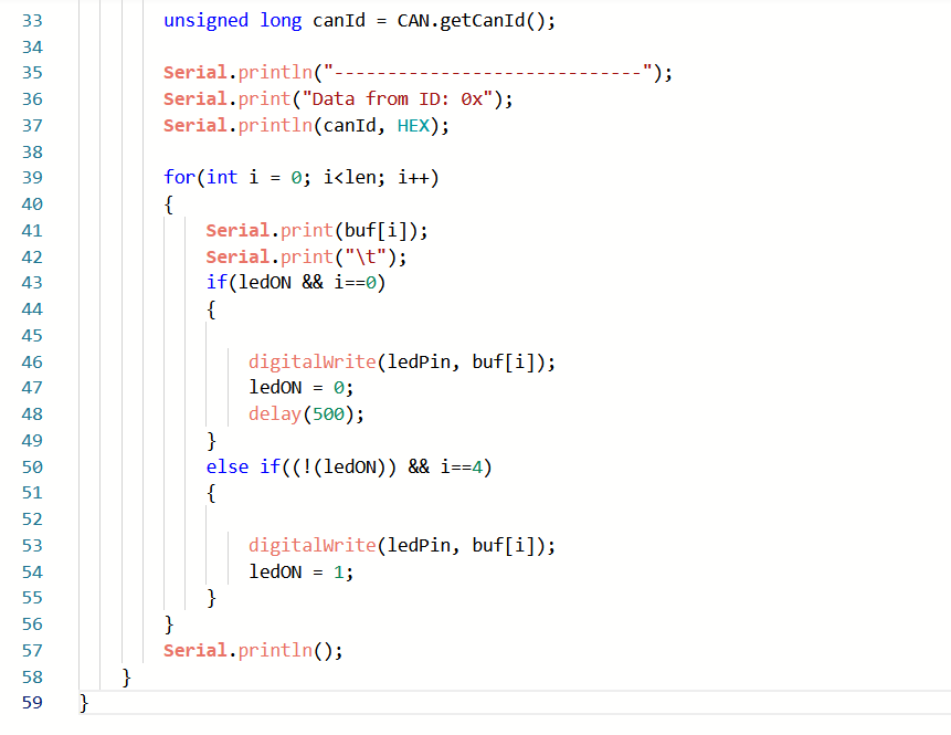
Receiver Code
How it works
Overall, the CAN and SPI libraries ensure the project operates as expected. You must deliver messages ranging from 0 to 8 bytes because of the CAN message-based communication approach.
So this project’s transmitter will deliver a 1 1 2 3 0 5 6 7 message, which transmits over the CAN bus. Afterward, the message gets sent to the receiver before showing up on the serial monitor.
The receiver obtains the 0th and 4th bit (1 and 0) from the sequence. As a result, the LED, which connects to Arduino’s pin 2, will power on and off.
MCP2515 CAN Applications

Robots commonly feature the MCP 2515 CAN module.
The MCP2515 CAN module has varying applications. You can find a few examples below:
- Electronic Gear Shifting System
- Primary automation interface
- Robots
- Automation
- A car engine’s auto start and stop function
- Medical equipment
Summary
Overall, the MCP 2515 relies on CAN to transmit and receive messages between multiple devices. For this reason, it serves as a practical communication protocol for many industrial and automotive applications. Not only that, but it also offers other features, including TJA1050 high-speed IC and MCP 2515 IC integration. You can even allow this device to communicate with microcontrollers via the SPI interface. However, you will need two CAN bus modules to achieve 1MB/s communication transmission.
Do you have any questions regarding the MCP 2515? Feel free to contact us!
Special Offer: Get $100 off your order!
Email sales@ourpcb.net to get started!