With the onset and continuous advancement in technology, safety and convenience are the names of the game. Every manufacturer aims to develop and design systems to make their customers' lives easier while enhancing their security. A timer switch circuit is one innovation that meets these basic needs. In this article, we define timer switch circuits, learn how they work, how you can make one at home, and the advantages of a timer circuit.
Read on to learn more.
Contents
- What is a Timer Switch Circuit?
- How does a Timer Switch Circuit Work?
- Applications of a timer Circuit
- Operating modes of Time Switches
- How to Make a Timer Switch Circuit
- Materials you will need.
- Procedure
- Working principle
- Points to note when making and using your timer circuit
- Benefits of a Timer Switch Circuit
- Summary
What is a Timer Switch Circuit?
A timer switch circuit is a circuit built to provide time gaps before activating a load. You, the user, can preset these time gaps.
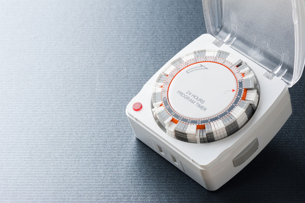
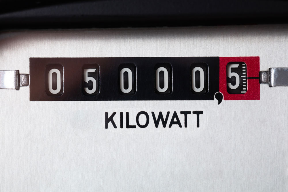
A 24-hour program timer
A timer switch circuit enables the connection or disconnection, switching on and off an electrical device or system at previously set times or intervals.
Generally, there are two main types of timers
- Mechanical timers
- Electrical timers
How does a Timer Switch Circuit Work?
When an electric current passes through a timer switch circuit, it triggers an oscillator; it then starts pulsating or throbbing.
The timer switch circuit counts these pulses and initiates specific actions once the oscillator makes several pulses.
Some actions that the timer switch circuit can initiate include turning off the television after a preset time.
For example, when you schedule your television to go off after two hours, you immediately turn it on, and the oscillator starts pulsating.
Once these pulses equal two hours, the timer switch circuit releases a bolt of energy that will turn off the television.
Special Offer: Get $100 off your order!
Email [email protected] to get started!
Applications of a timer Circuit
- Air circulation fans and systems
- Burglar protection alarms
- Security lights using outdoor timers
- Irrigation pumps and sprinkler systems
- Astronomical timers used in artistically arranged lighting
- Automatic fountain control systems
- Temperature control using a central heating timer
- Checking voltage using a current meter timer
Operating modes of Time Switches
There are four operating modes;
- Flicker Operation
- ON- delay operation
- Interval operation
- OFF – delay operation
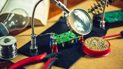
How to Make a Timer Switch Circuit
Below we learn how to make an IC-555 adjustable timer circuit since IC-555 timers are the most used timer circuits for home applications.
Materials you will need.
- Vero board
- 40 to 65w soldering iron
- Pushbutton
- Soldering gun
- Soldering wire that has flux
- Alternating current (AC) to (DC) Direct current converter 220V/12V
- Ceramic capacitors
- Resistors
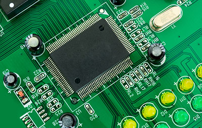
- 555 timer
Procedure
Place the IC-555 timer on the Veroboard, ensuring firmly in place.

Veroboard
Using your soldering wire, link the 100k preset (VR) PIN 6 to PIN 7
Next up is connecting the 10k resistance PIN 7 to PIN 8.
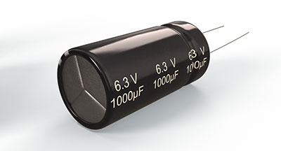
After your resistance pin is set, solder the 10uf/25v capacitor negative side on PIN 1. While also linking PIN two to PIN 6.
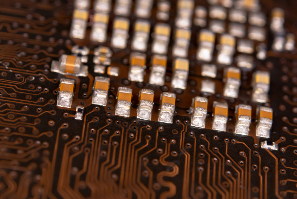
Ceramic Capacitors
Set the (100nf) capacitor PIN 5 to PIN one on the Vero board.
Ensure you put all the 4 LED joints parallel and on the negative of PIN 1
Solder the 470-ohm resistance PIN 3 to the LED positive.
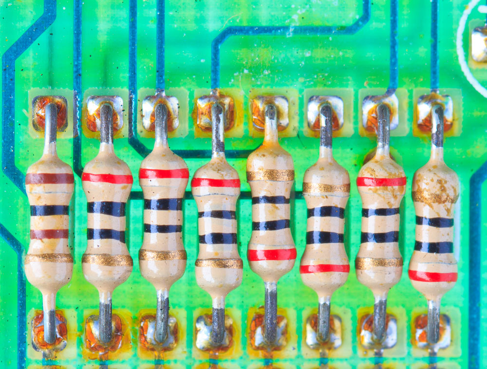
Resistors
Finally, connect the positive PIN 8 to PIN 4 and link the negative on PIN 1.
Your timer switch circuit is complete, and you can now test it to see how it works.
Follow the circuit diagram below for directions.
Working principle
When you apply pressure on the push button, you initiate the circuit by placing the trigger input.
Hence, the 555 timers will produce a pulse. The width the 555 timer makes is determined by your capacitor and resistor values.
Then a 12v relay drives the alternating current you connected to the output. The relay will stay on for a preset time you set using the potentiometer (pot) and then go off automatically.
You can set your IC-555 timer to go off or on periodically (duty cycles).
However, you should note that electric timers have cyclic switches, as they do not require a manual trigger.
An electric timer
For instance, the above circuit works well on a 1-10 minute timer.
It will thus go off or on, depending on your settings but within the minimum and maximum period.
To give you a more profound understanding of how the timer circuit works. Look at the ICC-555 block diagram below.
Where
Pin 1- Ground; the pin linking the negative supply rail to the timer
Pin 2- Trigger; when you place the flip-flop in an unfavorable position, the trigger moves the output switch from a low state to a high.
Pin 3- Output; drives the circuit and can source high amounts of current. That is why you connect LEDs to the output.
Pin 4- Reset controls movement of the output
Pin 5- Control Voltage; manages the ICC-555 timing by controlling the flip-flop (Switch)
Pin 6- Threshold; resets the switch when the voltage on the pin is more than 2/3Vcc.
Pin7- Links to the NPN transistor's internal connector and causes a slight delay after a power switch.
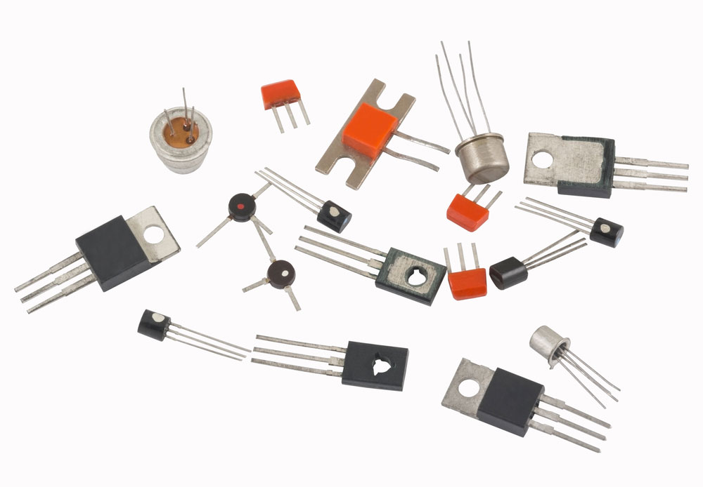
Transistors
Pin 8- Supply; acts as the power supply to the circuit.
Points to note when making and using your timer circuit
Only apply correct voltages that the timer can handle to avoid short-circuiting, as it may even lead to fires.
Connect the circuit parts precisely, as shown in the circuit diagram.
Benefits of a Timer Switch Circuit
A timer switch circuit;
- Saves Energy
- Alerts you on time spent
- Have plenty of applications
- Environmental Friendly
- Helps you monitor children's activities
- Enhances Safety
- Improves industrial productivity
Summary
Time switch circuits have helped revolutionize our lives through automation and provided us with enhanced safety.
You no longer have to walk around the house turning on lights thanks to time circuits. You also do not have to be scared when going on holidays or vacations as you will be confident in the safety of your home.
After reading this article, we hope you have fully grasped what time switch circuits are and learned how to make one at home effectively. For more information on the subject, feel free to contact ourPCB.
Special Offer: Get $100 off your order!
Email [email protected] to get started!