We can consider PCBs to be the heart of electronics. However, a single PCB isn’t enough to support an entire electronic device in most cases. This fact is especially actual for larger appliances. Thus, we need to expand the functionality of the PCB by adding and interfacing it with custom PCB manufacturing and external circuits. The best way to connect the PCB to other courses and devices is by using data buses, connectors, and connections. This guide will explore the FTDI line of serial TTL converters and cables. We will examine how they work, primarily focusing on FTDI pinouts and connecting them.
Contents
- FTDI Cables and Adaptors
- Types of FTDI Convertors
- USB to RS232 Converter Cable (exposed wires):
- FTDI USB to Serial Pinout Diagram
- FTDI Pinout Configuration and Details
- DTR (Data Terminal Ready):
- Setting Up the FTDI USB Converter
- Using the FTDI Device with Your Computer
- FTDI USB to Serial Applications
- Conclusion
FTDI Cables and Adaptors
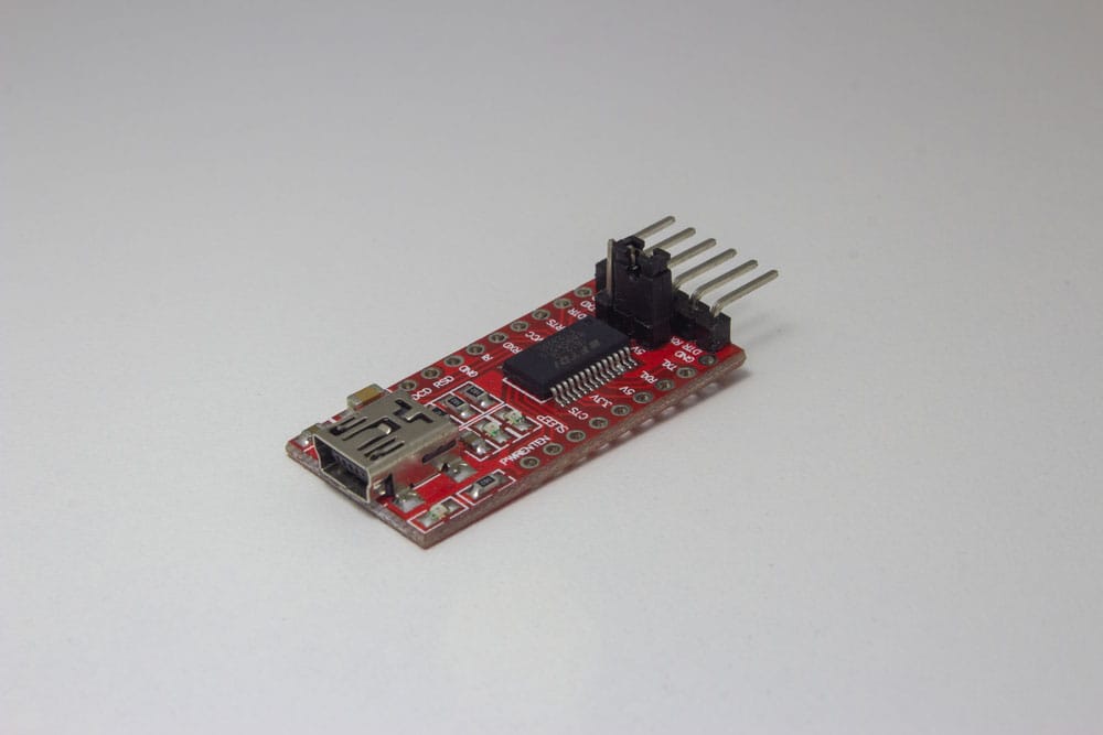
FTDI PCB converter used to program Arduino microcontrollers
FRDI’s main product list consists of converters in cables and adaptors. Their most notable products include USB to UART cables and RS485 interfaces. Additionally, they also provide integrated circuit packages that help facilitate conversions. Users can utilize these cables to connect and communicate to circuit board-based serial devices from their computers. Arduino’s offerings are a fine example of this. Nevertheless, let’s take a deeper look at the types of available convertors and categories.
Types of FTDI Convertors
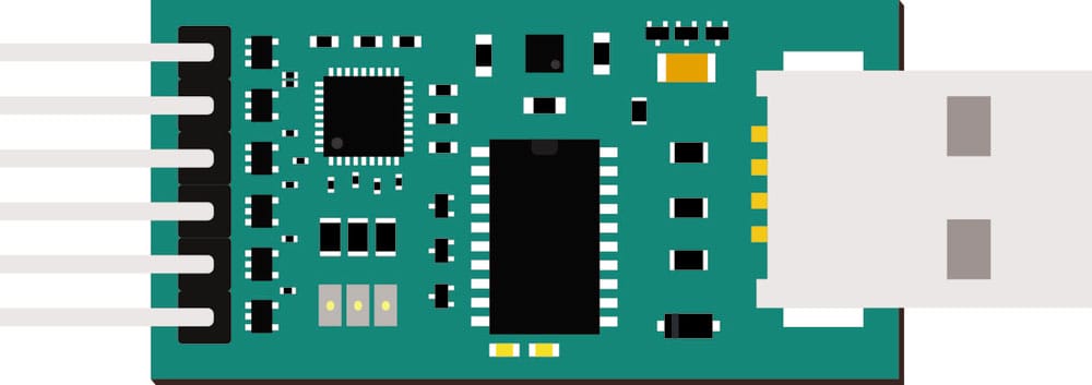
Vector image of USB to UART PCB
- USB to UART Audio Jack Cable: They allow you to connect a USB port to an auxiliary input. Essentially, you can connect a USB to an audio device. FTDI has options that can operate from 3.3 volts to 5 volts.
- USB to UART TTL Cable: It allows you to connect USB to serial ports that use the TTL interface. It uses a 6-pin connector for the serial connection. Again, FTDI has options that can output voltages of either 3.3V or 5V.
- USB to UART PCB Adaptor: Uses a small PCB with FTDI’s FT232R integrated circuit to convert USB signals into serial signals. In addition to its six header pins (2.45 mm), they tend to feature 18 through-hole connectors. Of course, it depends on the version of the adaptor. Furthermore, these devices come in 3.3V and 5V varieties.
-
USB to RS232 Converter Cable (exposed wires):
Connects from the USB port to an RS232 interface. Instead of a plug, these conversion cables use exposed wires to allow users to create custom connections. Transmission/communication speeds to RS232 devices can go from a minimum of 300 Bauds and reach a maximum of 1 MBaud. Furthermore, they generally have an output of 5 Volts.
- USB to RS233 Serial Interface PCB: A PCB-based converter that connects a serial device (either through cables or integration through soldering) to a USB-A port. It features data transfer rates of up to 1 Mbaud (from a minimum of 300 baud). Furthermore, these products tend to have operating temperature ranges between -40°C and 85°C.

Vector image of USB to RS233 cable
In addition to the above connectors and convertors, FTDI also provides USB to DB9M, DB9/VGA, and parallel COM ports. FTDI delivers a host of IC packages that enable USB slave to UART, JTAG, SPI, single and Dual PD, and FIFO conversion.
The latest FT232R chips feature preprogrammed and integrated EEPROM. Furthermore, they boast lower operating and suspended current than their predecessors. The FT232R chips also provide UART pin signal inversion and low USB bandwidth consumption.
FTDI USB to Serial Pinout Diagram
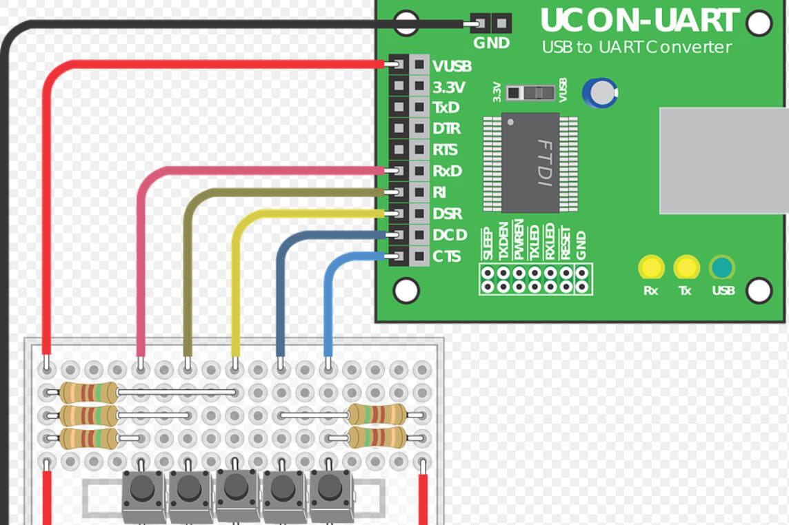
USB to UART converter connection diagram
The above connection diagram displays the pinout placement of PCB-based USB to UART converter. The converter in the above Image features an FTDI IC. Additionally, it has a selection switch to select the output current. You have the choice between the 3.3V and a VUSB output (5V). Furthermore, the diagram illustrates a breadboard connection using the pinouts on the converter.
Because the breadboard uses the VUSB to pin to draw power, the switch on the converter is set to the VUSB position. Ultimately, you need four pins to communicate or exchange data between the USB device and the breadboard. Nevertheless, we’ll expand on these pinouts in the next section.
FTDI Pinout Configuration and Details
This section will explain each pin on the FTDI serial interface to the USB module. You can use the above cable pin diagram as a reference.
V-USB: A pinout that uses power from the USB port to provide a 5-volt current to the data carriage/reception (serial/UART) device. Consequently, the ground pin is unnecessary since the carrier derives its power from the USB port, which already has innate grounding.
3.3V: A pinout that acts as a common power source. Essentially, it sends 3.3V output from the data transmission device (USB) to the output/data carriage device (serial /UART). Again, this will most likely receive the current from the USB device unless we connect an external power source to the converter.
TxD (Transmit Asynchronous Data): An output pin that allows you to transmit asynchronous data from the data transmission device (USB) to the data carriage/reception device (serial/UART).
DTR (Data Terminal Ready):
This pinout enables the USB device to check if the serial carriage device is ready for communications.
RTS (Request to Send): This pinout allows you to control data flow from the USB to the serial device. Along with the CTS pinout, it helps test and displays the status of the sender (USB) and receiver (RS232/UART).
RxD: (Receive Asynchronous Data): An input pin that allows the data transmission device (USB) to receive asynchronous data or serial traffic from the data carriage device (serial/UART).
RI (Ring Indicator): We use this pin to detect and display communications to the data carriage device (UART). It helps with debugging.
DSR (Data Set Ready): Sends a signal indicating that the transmission device (USB) is ready to send communications or data to the carrier device (serial/UART).
DCD (Data Carrier Detect): Assists in detecting if the carrier device (serial/UART) receives communications from a remote serial device. Additionally, we can use this pin for device debugging purposes by connecting it to a LED.
CTS (Clear to Send): Detects and indicates that the data carrier/reception device (serial/UART) is ready to accept data from the data transfer device (USB). Again, we can also use this for debugging purposes by connecting this pin to a LED or light source.
Special Offer: Get $100 off your order!
Email [email protected] to get started!
Setting Up the FTDI USB Converter
In most cases, the serial device or module you’re connecting to the converter will have corresponding or opposing input and output pins.
The above Bluetooth module has six pins. You can keep the Key pin unused. The VCC (voltage at common collector) receives a current to power the Bluetooth module. Typically, you’ll connect it to the VUSB or +5V pin on the converter.
The GND pin on the module should connect to the GND on the converter. In cases where the converter doesn’t have a ground pin or slot, you can leave it disconnected on the Bluetooth module. Again, the converter will use innate grounding from the USB device.
The TxD pinout on the Bluetooth module will connect to the RxD input pin on the serial converter. This connection allows the Bluetooth module to send communications to the converter and the USB input device.
It allows your USB device to send asynchronous data to the Bluetooth module. The Bluetooth module will broadcast this data as radio signals. Likewise, the TxD pinout on the converter will connect to the RxD input pin on the Bluetooth module. Of course, it depends on whether you’ll be using the Bluetooth serial device for both transmission and reception.
You don’t have to connect the State pin to any pinouts on the convertor. However, you must connect it to either the CTS, DCD, or DSR pins on the FTDI device if you decide to. Again, your connections will be dependent on the purpose of your configuration. For example, you can use the CTS pinouts to strictly ice transmit data from the USB device to the Bluetooth device.
Using the FTDI Device with Your Computer
You will most likely use your FTDI converter device to connect a serial device to a computer. In some cases, the device will be a microcontroller or module that requires programming. Nevertheless, every device that connects to your computer involves a set of drivers to work.
The latest versions of Windows will automatically try to find the correct drivers for your device. Alternatively, you can manually download FTDI drivers from the official website page.
If you’re using the FTDI converter to connect your PC to a communications device, you’ll need the right software to facilitate data transmission. Putty seems to be the best open source and free solution for this purpose. However, if you’re using the FTDI converter to connect a microcontroller to your computer, you can use the proprietary software to program it.
FTDI USB to Serial Applications
There are various modules and serial devices you can use along with the FTDI’s cables and converters. However, you first need to ensure that the module or device you use is compatible with the FTDI’s pinouts. Here’s a summary of the most useful applications:
- Parallel port to USB conversion (for older printers)
- Bluetooth module to USB connection (enables Bluetooth connectivity on personal computers)
- Smart and micro SD card readers to USB connections
- Microcontroller and SBC programming
- GPS module connection to PC via USB
- RFID readers to PC USB connection
Conclusion
This guide explored the importance of FTDI conversion cables and devices. Furthermore, we covered the purpose of the FTDI pinouts and some of FTDI’s available chips. It would help if you now had a basic understanding of these topics. At least enough to integrate some of FTDI’s conversion products into your next PCB or breadboard-based project. Moreover, you can use the information in this guide to build your FTDI chip adapter using the FT232RL. Nevertheless, we hope that you’ve found this article to be helpful. As always, thank you for reading.
Special Offer: Get $100 off your order!
Email [email protected] to get started!