Do you have any knowledge of first-order circuits? Most people don't know about them. This lack of knowledge is why they can't understand them. These circuits are fundamental for building any circuit board. So, you must know what a first-order course is and how it works. You will need this information if you want to develop PCBs (Printed Circuit Boards). This article will ensure that you have all the fundamental knowledge regarding a first-order circuit.
Contents
- 1、first order circuits--What are First Order Circuits?
- 1.1 One Energy Storage Element
- 1.2 first order circuits--Contains Resistance
- 2、Types of First-Order Circuits
- 2.1 RC Circuits
- 2.2 RL Circuits
- 3、first order circuits--Source Free Circuits
- 3.1 first order circuits--Definition
- 3.2 first order circuits--Transient Response
- 4、Step Response- RC Circuit
- 4.1 first order circuits--Complete Response
- 4.2 Calculating Complete Response
- 4.3 first order circuits--Shortcut Method
- 5、first order circuits--Additional Information
- 5.1 First Order Transient Circuits
- 5.2 first order circuits--Time Constant
- 6、first order circuits--Conclusion
1、first order circuits--What are First Order Circuits?
First, we have to determine the characteristics of first-order circuits. A first-order course can be solved using first-order differential equations. They can build simple circuits very quickly. You need a few items to make a first-order circuit.
1.1 One Energy Storage Element
A single energy storage element characterizes every first-order circuit. It can either be a capacitor or an inductor. The capacitor stores electric charge while the inductor stores are current. A first-order circuit can only have one of the two present but not both.
1.2 first order circuits--Contains Resistance
Each first-order circuit is incomplete without a resistance. It is up to you to connect the opposition with the capacitor or the inductor in the course. You can connect it in series or parallel with the source.
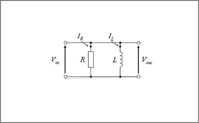 Image 1: First Order Circuits
2、Types of First-Order Circuits
First-order circuits are of two major types. They are RC and RL circuits, respectively. The RC circuit involves a resistor connected with a capacitor. The RL circuit has an inductor connected with the resistor.
2.1 RC Circuits
According to Wikipedia, an RC circuit can have a voltage or a current source. If there is a source present, it is going to charge the capacitor. When the head is removed, the capacitor will begin to discharge. You can connect the resistor and the capacitor in either series or parallel with each other. However, series RC circuits are more useful than parallel RC circuits. Series RC circuits have a variety of different applications. They have been used in relaxation oscillators and strobe lights, pacemakers, and intermittent windshield wipers. RC circuits can be used as filters to filter out any unwanted frequencies.
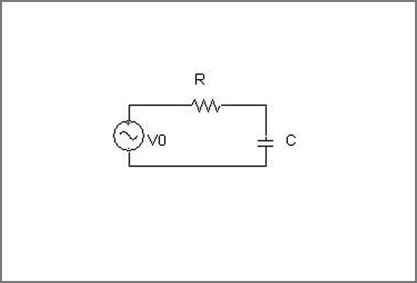 Image 2: First Order Circuits
2.2 RL Circuits
The source in an RL circuit can either be a voltage or a current source. In a series RL circuit, the resistor and the inductor are connected in series with each other. For such courses, the recent passing through the resistor and the inductor is the same. In a parallel RL circuit, the inductor and the resistor are connected in parallel, and the voltage across the resistor and the inductor remain the same.
Series RL circuits mostly use in devices instead of parallel RL circuits.
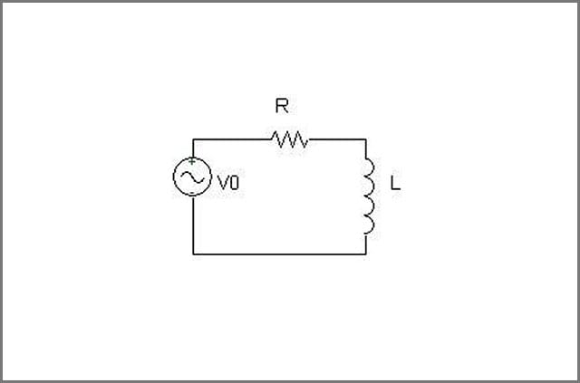 Image 3: First Order Circuits
Special Offer: Get $100 off your order!
Email sales@ourpcb.net to get started!
3、first order circuits--Source Free Circuits
3.1 first order circuits--Definition
As the name implies, source-free circuits don't have ahead. Any independent sources that were initially connected to the circuits were removed to create a source open. Some switch action has to take place before the seed is removed, though. So, in short, germ-free circuits are first-order circuits without a source. Source open circuits are of two major types, too, source-free RC circuits and source-free RL circuits. Such courses are even more straightforward than the first-order circuits. Therefore, they can be analyzed easily.
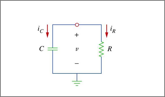 Image 4: First Order Circuits
3.2 first order circuits--Transient Response
The currents and voltages in source-free circuits have a transient response. That is because of the initial inductor current and capacitor voltage. These initial conditions are due to the source connected to the course in the beginning.
The inductor and capacitor connected to the circuit will store some current or voltage during the initial stages before the source is removed. Then the inductor or the capacitor will become the energy source for the circuit. This energy will dissipate slowly until the stored voltage or current in the capacitor or the inductor reaches zero.
4、Step Response- RC Circuit
The step response is the response of a circuit to an abrupt change in its existing conditions, like a sudden step up in voltage. The step response measures how the circuit's current and voltage adjustments to the new terms. In this section, we will discuss the step response of an RC circuit.
4.1 first order circuits--Complete Response
The complete response of an RC circuit to a voltage step summarizes its natural and forced responses. The natural response focuses on the energy stored inside the capacitor, its initial voltage. It shows the changes in the circuit as life slowly dissipates.
The natural response ignores the step up in voltage. Conversely, the forced response ignores the initial voltage of the capacitor. Instead, it focuses on the output voltage of the capacitor and how it will change as the circuit loses its stored energy.
Both forced and natural response only tells half of the story and have their limitations. Therefore, the superposition concept is used to combine the two. It will give us the complete or total response of the RC circuit to the step in voltage.
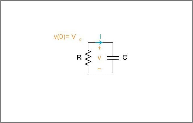 Image 5: First Order Circuits
4.2 Calculating Complete Response
The first step in calculating the complete step response of an RC circuit is to calculate the natural response and the forced response separately. When calculating the natural response, the input voltage is considered to be zero.
Conversely, when doing the calculations for the forced response, we think the initial energy of the capacitor to be zero. These considerations simplify the equations, making it possible for you to solve the different differential equations. It converts the non-homogenous differential equation into a homogenous one, which is easier to solve.
Solving a homogenous differential equation is more accessible than a non-homogenous one. That is why directly calculating the complete response of an RC circuit after a step up in voltage is not an option.
4.3 first order circuits--Shortcut Method
Step response of the RC circuit can be calculated using a shortcut method too. This shortcut method doesn't involve the use of a differential equation. Instead, you can calculate the step response for the capacitor voltage using the following simple equation.
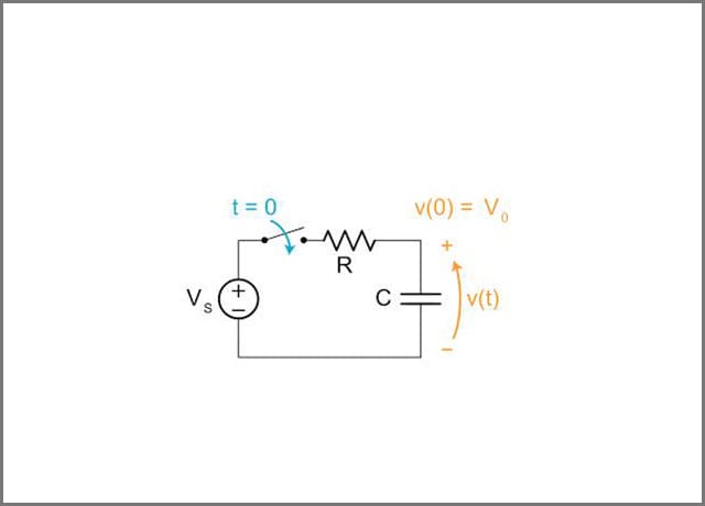 Image 6: First Order Circuits
5、first order circuits--Additional Information
5.1 First Order Transient Circuits
First-order circuits that see a change in their initial conditions show a transient response. Any change in the voltage or the current can produce this response. You will have to solve the capacitor's voltage to calculate the quick reply for an RC circuit.
Similarly, you will have to settle for the inductor's current to calculate the transient response for an RL circuit. It would help if you considered the course as short when solving for the inductor's current. However, it would help if you considered it as open when solving for the capacitor's voltage.
You can apply the KCL (Kirchhoff's Current Law) and KVL (Kirchhoff's Voltage Law) for circuits with inductors and capacitors, respectively. After using KVL or KCL, you can get simple differential equations that are easy to solve.
5.2 first order circuits--Time Constant
In a short first-order circuit, the time constant determines the speed of the transient response. It is calculated in seconds and represented by the Greek letter tau (τ). Courses that have a lower value of the time constant can conform to the new conditions very quickly. Circuits with high costs of time always take a lot of time to reach a steady state. Calculating the time constant is essential for a first-order transient course. It can tell how long the short phase of the circuit will last.

6、first order circuits--Conclusion
First-order circuits are simple circuits that have a resistor connected with an energy storage element. It is either a conductor or an inductor. The first-order circuit with just a resistor and a conductor is called an RC circuit, while one with a resistor and an inductor is called an RL circuit. A first-order circuit whose source has been removed is termed a free source circuit. Open source circuits have a transient response, which is due to the initial conditions of the course before the removal of the source. Changes in the voltage of an RC circuit can elicit a reaction from the voltage of the capacitor.
Special Offer: Get $100 off your order!
Email sales@ourpcb.net to get started!