About MPU6050 Pinout, Advanced navigation systems relied on sensors, but everything changed when engineers micro-machine them to fit in tiny chips.
With such a small size, low cost, and low power consumption, the sensor made its way into almost every electrical device for augmented reality, gaming, fitness monitoring, etc.
But what if you combine a gyroscope and an accelerometer sensor in one circuit board fabrication? The result is the MPU6050 chip, and it gives incredibly accurate data about an object's orientation. Here is a close-up look at the module and how you can link it with an Arduino MCU for your project.
Contents
- What is MPU6050 Pinout?
- MPU6050 Pinout Configuration
- MPU6050 Pinout--MPU6050 Features
- MPU6050 Pinout--MPU6050 Sensor Module: Gyroscope + Accelerometer
- 3-Axis Gyroscope
- 3-Axis Accelerometer
- Alternative for MPU6050
- MPU6050 vs. MPU6000
- Interfacing MPU6050 with Arduino
- Library Installation
- Data Reading
- MPU6050 Applications
- Summary
What is MPU6050 Pinout?
An MPU6050 module is a Micro-Electro-Mechanical System (MEMS) that measures velocity, displacement, dynamic/static acceleration, orientation, angular momentum, and other motion-related parameters.
At its heart is an inexpensive, low-power, 6-axis motion tracking chip with three parts. First is a 3-axis accelerometer, second is a 3-axis gyroscope, and third is a Digital Motion Processor (DMP).
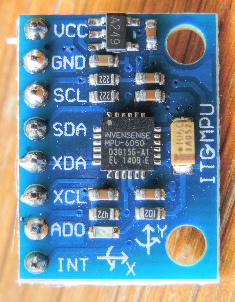
An MPU6050 module
Source: Wikimedia Commons
These three fit in a tiny 4mm x 4mm package mounted on a circuit board with a 3.3V regulator.
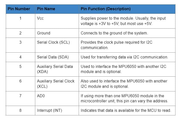
MPU6050 Pinout Configuration
The MPU6050 module features the following eight main pinouts.
MPU6050 Pinout--MPU6050 Features
- MEMS 3-axis accelerometer and 3-axis gyroscope values combined
- Power Supply: 3-5V
- I2C communication protocol
- Built-in 16-bit ADC delivers high accuracy
- Built-in DMP provides high computational power
- Configurable I2C address
- In-built temperature sensor
- Can interface with magnetometers and other I2C devices
Special Offer: Get $100 off your order!
Email sales@ourpcb.net to get started!
MPU6050 Pinout--MPU6050 Sensor Module: Gyroscope + Accelerometer
As explained earlier, an MPU6050 module features three parts, but the gyroscope and accelerometer are responsible for taking measurements. Here's how they work.
3-Axis Gyroscope
A gyroscope measures angular rotation by using the Coriolis Effect. When the gyroscope rotates around the X, Y, or Z-axis, the Coriolis effect creates a vibration that the MEMS detects.
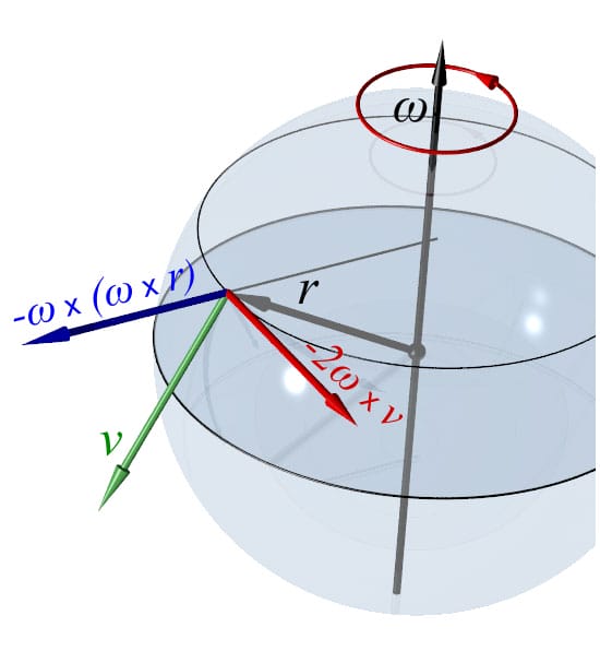
The Coriolis force
Source: Wikimedia Commons
However, the MEMS gyroscope is quite different from the traditional design because it contains a proof mass with four parts. These parts are always in a continuous oscillating movement, moving in and out simultaneously in a horizontal plane. By doing so, they react to the Coriolis effect, which the MEMS detects.
The module then amplifies, demodulates, and filters the detected signal to produce a voltage proportional to the angular velocity.
A 16-bit ADC scans each axis then digitizes the voltage signals to give the angular velocity in degrees per second.
3-Axis Accelerometer
On the other hand, an accelerometer measures proper acceleration, which refers to the rate of velocity change of a body in its rest frame. The MEMS accelerometer consists of a micro-machined structure with a suspended mass and fixed plates suspended on silicon springs that sit on a silicon wafer.
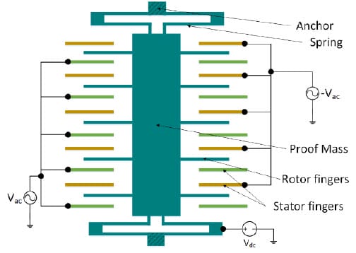
The structure of an accelerometer
Source: Wikimedia Commons
The springs allow the structure to move freely and deflect when acceleration occurs on one axis. This movement creates an imbalance in the differential capacitor, which causes a change in capacitance proportional to the acceleration. The capacitance forms the sensor output, which the 16-bit ADC digitizes into a g unit (gravity).
The module continuously measures 1 g on the Z-axis on a flat surface due to gravity, but the X and Y axes measure 0 g.
Alternative for MPU6050
The alternatives you can use in place of the MPU6050 include the following:
- ADXL335 (3-axis accelerometer)
- ADXL345 (3-axis accelerometer)
- MPU9250 (9-axis IMU)
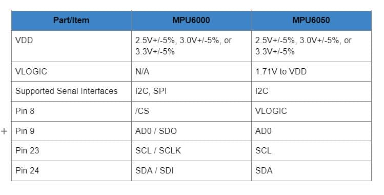
MPU6050 vs. MPU6000
Even though the two are identical, they have some differences, such as in the supported serial interfaces and VLOGIC reference pins. The following table summarizes all these differences.
Interfacing MPU6050 with Arduino
As stated earlier, the MPU6050 module comes with a 3.3V regulator mounted on the same board, and you can use it with the 5V Arduino logic microcontroller. Wiring it with Arduino is quite simple, and you should begin by linking the 5V Arduino output to the Vcc pin while the ground pin goes to GND.
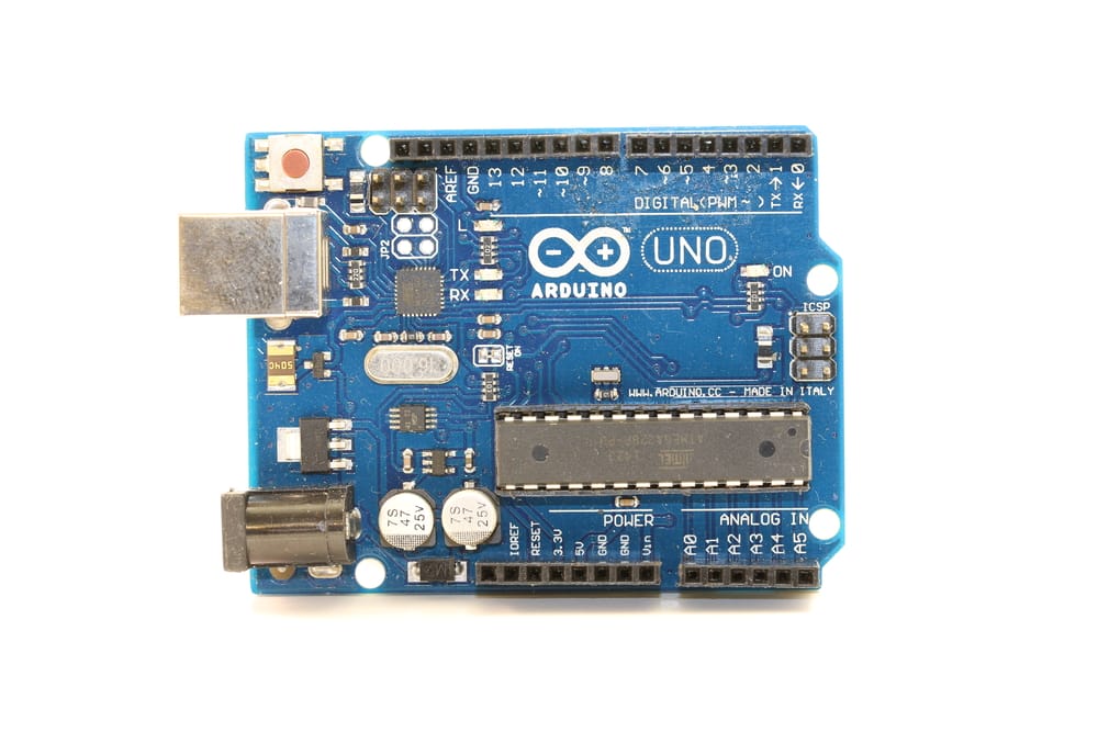
An Arduino UNO microcontroller. Note the connecting pins.
After linking those two, the remaining part is the I2C connection, and Arduino boards have different I2C pins. However, boards with the R3 layout have the SCL (clock line or A5) and SDA (data line or A4) near the AREF pin.
Use the following table to guide you in the I2C connection when using different Arduino boards.
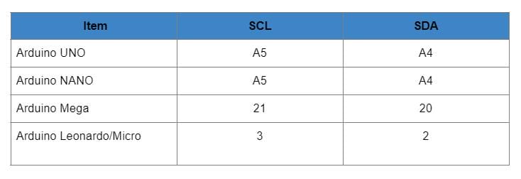
You can connect the two directly or via a breadboard.
Library Installation
Next, you need to create an I2C interface between two via the Arduino IDE using a library to enable them to communicate. Even though capturing raw data from the module is easy, translating it into meaningful information is tricky. Libraries simplify this process, and you can use the Adafruit Unified Sensor Driver plus the Adafruit Bus IO Library.
How to install a library in the Arduino IDE
Source: Wikimedia Commons
Alternatively, you can use Jeff Rowberg's Arduino library, which has two example programs. The first gives raw values, while the second optimizes them using the DMP.
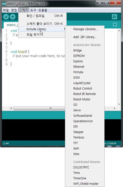
Go to Sketch > Include Library > Manage Libraries to install the libraries, then allow the library manager to download them and update the installed library list.
Next, filter your search in the Library Manager window by typing "MPU6050". Look for the specific library, then install it.
Data Reading
Once everything is up and running, you must set the serial monitor to a baud rate of 115200. The module sends a lot of data, so this high rate is necessary to display the data on the screen.
Arduino code will give you a clear understanding of how to read angular acceleration, linear acceleration, and temperature from the module. As you get data about these three parameters, try to move the module to see how the readings change.
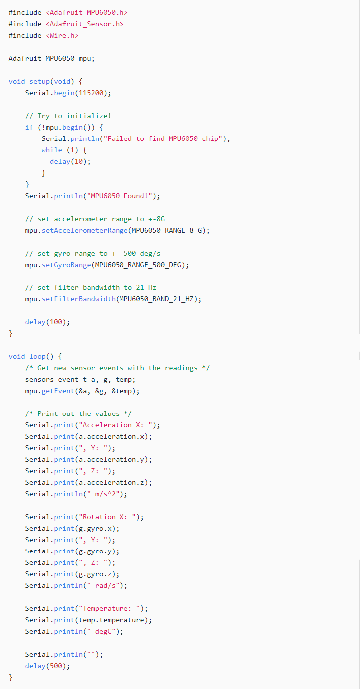
Arduino code
Once you understand what's going on, it will give you a base to experiment on other more practical projects.
In addition to reading the data, you should consider plotting it to visualize the module's sensor outputs better as you move it.
Graphs make things easier to understand, and Arduino features a Serial Plotter tool to help visualize the data while troubleshooting the code. But for the plotter to work correctly, remember to set its baud rate to 115200.
Arduino captures the readings every ten milliseconds, then plots a continuous 2D line graph.
MPU6050 Applications
You can use the MPU6050 module in the following applications:
- IMU measurement
- Drones / Quadcopters for direction control
- Self-balancing robots and robotic arm controls
- Humanoid robots

A humanoid robot (Sophia)
- Tilt sensor
- Handsets and portable gaming devices
- Motion-based game controllers

Wii Remote Plus and Wii Remote game controllers
Source: Wikimedia Commons
- Rotation or orientation detectors
- 3D remote controls for set-top boxes and internet-connected DTVs
- 3D mice
Summary
To conclude, the MPU6050 Pinout is a vital piece of hardware with numerous applications in modern-day electronic devices. However, as a developer, the best way to test and use the device is by linking it to an Arduino microcontroller. The steps above should help you set everything up and get right to work.
If you need the module for your project or have any questions about how to interface it with Arduino, get in touch, and we'll answer your queries.
Special Offer: Get $100 off your order!
Email sales@ourpcb.net to get started!