Microwaves transmit data at high frequencies. Therefore, PCBs for microwave devices should handle high-power signals optimally. However, microwave applications vary nowadays, from military use to consumer electronics. Thus, you need to pick the best material for the specific application.We have covered the best microwave circuit board material and properties for the most typical ones to help you pick the right one for your project. Take a look!
Contents
- What are Microwave Circuit Boards?
- Microwave PCB Advantages
- RF/Microwave PCB Layer Stacks
- Key Parameters To Consider When Choosing RF/Microwave Circuit Board Materials
- Dielectric Permittivity
- Loss Tangent
- Surface Roughness
- Thermal Conductivity
- Dielectric Strength
- Best RF/Microwave Circuit Board Materials
- Isola PCB Laminates (High-Performance)
- Rogers Advanced Materials for RF/Microwave Designs
- Arlon Electronic PCB Materials
- Taconic Advanced Dielectric Materials
- Panasonic MEGTRON 6
- Higher Dk Materials
- PA Materials
- Metal Material for Microwave PCB
- FR-4 Material
- PTFE (Teflon) for Microwave PCB
- Is PTFE Better Than FR4 PCB Materials?
- Common RF & Microwave PCB Materials’ Dielectric and Material Properties
- How do RF and Microwave PCB Differ?
- Common Challenges and Solutions for RF and Microwave PCB Designs
- Noise
- Impedance Matching
- Return Loss
- RF/Microwave PCB vs. Normal PCB: Differences in Material, Design, and Manufacturing
- Materials
- Design
- Manufacturing
- OurPCB: Your Best RF/Microwave PCB Manufacturer in China
- Summary
What are Microwave Circuit Boards?
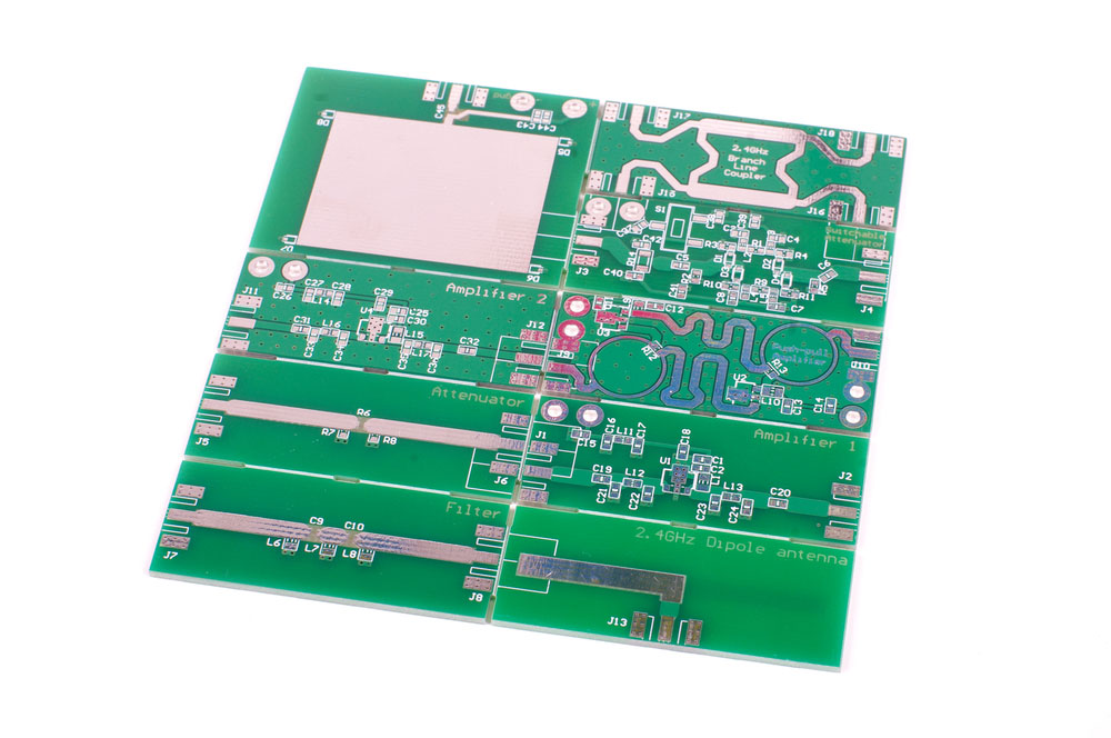
Microwave circuit boards are special radio frequency PCBs designed to work at signal frequencies in the megahertz to gigahertz range.
These medium to extremely high frequencies are ideal for various applications, such as military radars and smartphones.
The board requires special materials and technology to achieve this performance.
A microwave PCB
Microwave PCB Advantages
Microwave circuit boards have the following advantages.
- High Speed: The low consistency and tangent of the signal loss enable faster and less impudent transmission.
- High Stability: Microwave PCBs are stable at extreme temperatures and can run analog applications at 40 GHz.
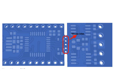
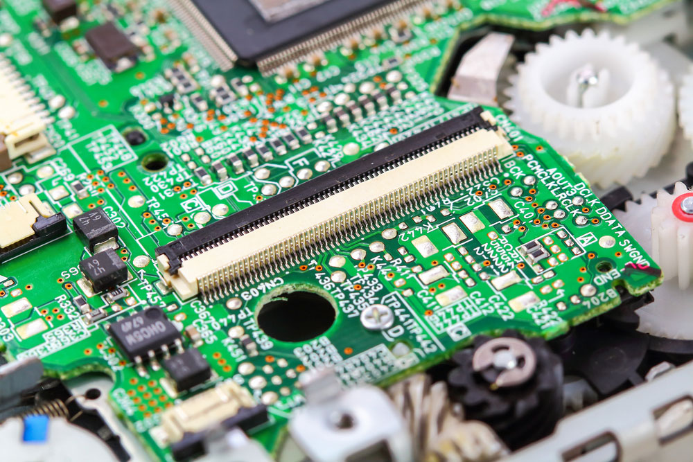
- Efficient Fine Pitching: You can mount fine-pitch components on the board efficiently without any issues.
A fine-pitch PCB assembly
- Multifaceted: You can also create multilayer boards by aligning the layers into intricate patterns using low CTE components.
- Reduced Costs: It is possible to mix the materials in a panel storage system. This action lowers assembly costs while optimizing PCB performance.
RF/Microwave PCB Layer Stacks
One of the most important factors when designing a microwave PCB stack is the material to use in each layer. The five primary layers include the prepreg/bond ply, laminate, copper foil, copper pad surface plating, and surface coatings (conformal coatings, solder masks, etc.).
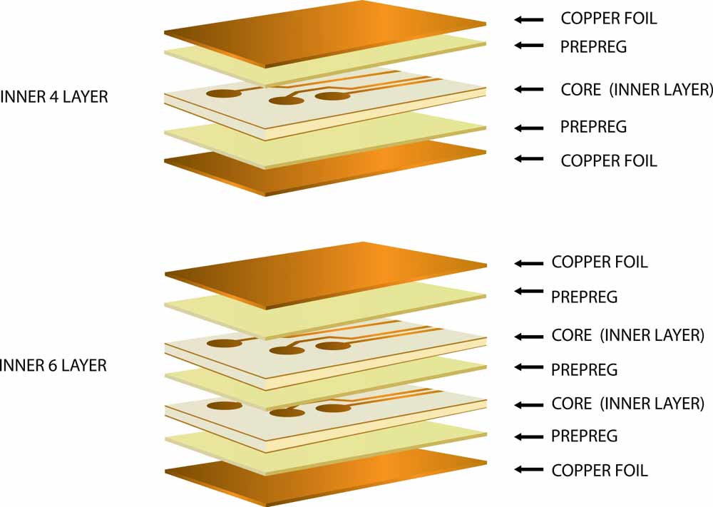
PCB layer stacks for multilayer boards
The laminate and prepreg or bond ply separate the conductive copper layers and provide insulation, so they should be low-loss dielectric materials, such as PTFE. This engineered thermoplastic fluoropolymer material exhibits low dielectric losses even when the copper layer is transmitting signals at microwave frequencies.
Arlon, Rogers, and Taconic are quite popular for this application as well, but PTFE is the most prevalent.
Key Parameters To Consider When Choosing RF/Microwave Circuit Board Materials
These electrical and mechanical properties make microwave PCB materials suitable for different applications.
Dielectric Permittivity
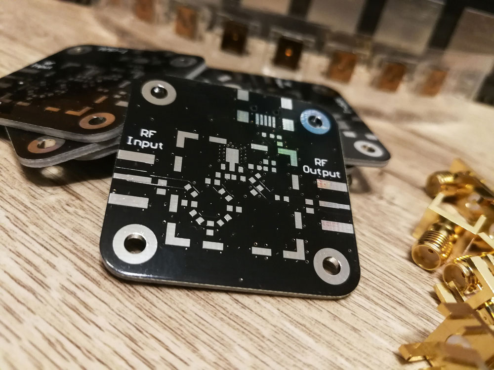
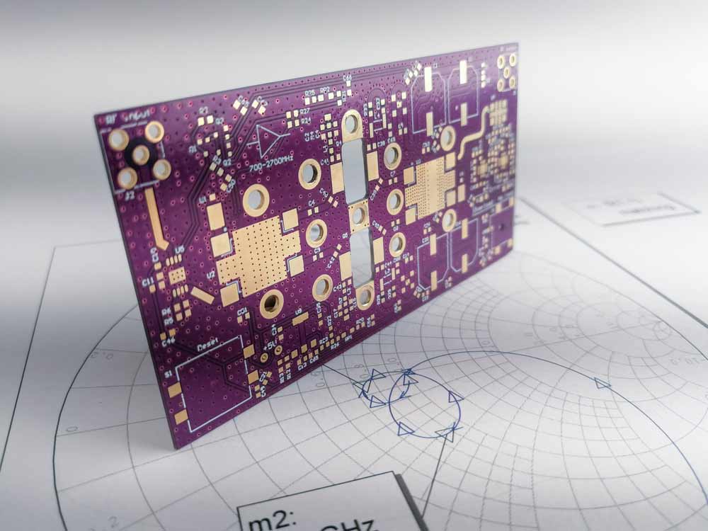
Also known as relative permittivity, dielectric permittivity shows the measure of a material's dielectric properties relative to the dielectric properties of air at room temperature. This property is a function of frequency and affects the behavior of electric fields passing through the material. A low dielectric is better for high-frequency signals because it reduces parasitic capacitance between the conductive structures and copper traces. Additionally, permittivity determines planar structure geometries.
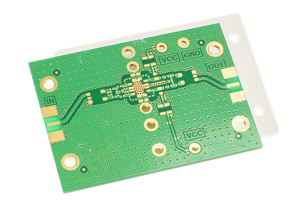
A high-frequency amplifier PCB
Loss Tangent
The dissipation factor or loss tangent gives a measure of the electromagnetic energy absorbed in the material and dispersed as heat. The property is also a function of frequency. Low-loss tangent materials are ideal for high-power and high-performance applications because they reduce losses in the transmission lines.
Surface Roughness
Surface smoothness or roughness can affect performance depending on the application. This interference usually affects the layer depositing resolution and adhesion characteristics.
Thermal Conductivity
Thermal conductivity measures how well materials conduct heat. Poor thermal conductivity can limit a device's performance by minimizing the stack's overall thermal conductivity.
Dielectric Strength
This property measures the required electric field strength to begin stripping electronics from the dielectric material. It is a vital property for high voltage and power applications because it can limit performance.
Best RF/Microwave Circuit Board Materials
There are several microwave PCB materials, but the following are the top 10.
Isola PCB Laminates (High-Performance)
Isola has been a pioneer in manufacturing and developing copper laminating solutions for multifaceted PCBs since 1912.
The best material options should have a perfect balance between efficiency and price. Isola laminates for microwave frequency circuits provide steady and accurate dielectric, dielectric, and layer thickness management.
Rogers Advanced Materials for RF/Microwave Designs
is one of the oldest PCB laminate manufacturers because they created the first material for RT/droid in 1949. This material is currently the market leader in high-speed microwave PCB applications in the high-frequency PTFE family. PCB PTFE laminates need unique materials and systems to produce. Teflon is the most famous brand name for PTFE-based formulations.
Arlon Electronic PCB Materials
Arlon specializes in the acrylate resin technique, a material that incorporates extraordinary TG, polyimide, and low-cost thermoset structures. The company based these resin alternatives on multiple substrates, such as non-plaited aramid and fabric crystals. These substrates are perfect for reliable, high-speed PCB microwave signals.
Taconic Advanced Dielectric Materials
is a global leader in PTFE products. The company primarily focuses on manufacturing thermally stable materials with a low dielectric constant for microwave and RF applications. Also, some of these laminates provide exceptional loss insertion capabilities with an ultra-low fiberglass percentage and standard refractive index on the cover.
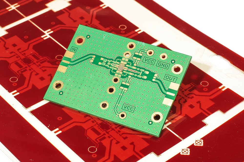
A RF PCB
Panasonic MEGTRON 6
This laminate is a sophisticated PCB technology for induction motors used in high-frequency measurement equipment, data centers, IC testing systems, etc. Also, the material has low dielectric factors and dissipation, high thermal expansion, and low transmission losses.
Higher Dk Materials
If looking for laminates for power amplifiers and low noise amplifiers, you need materials with high Dk values. These can miniaturize circuit dimensions for a specific frequency range and impedance.
The circuit wavelength also depends on the laminate material and frequency. Higher Dk values enable routing algorithms to operate at lower frequencies.
PA Materials
Susceptibility control and tight Dk are significant factors for laminates used in PA (Power Amplifier) circuits. The additional heat generated by these circuits also means thermal conductivity is a weighty factor. Other vital properties to look for are CTE (coefficient of thermal expansion), TCDk, and heat capacity.
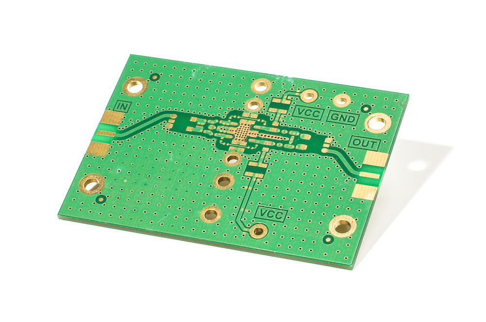
An RF amplifier PCB
Metal Material for Microwave PCB
Iron, copper, aluminum, and other metallic PCB materials are ideal for surface mounting and are more durable (mechanically). Pick the specific metal material based on the expected results.
FR-4 Material
is a glass-reinforced laminate epoxy material. It is the most often used PCB material because it is waterproof, has high tensile strength, and provides outstanding weight.
PTFE (Teflon) for Microwave PCB
Teflon is a zero-resistance polymeric substance suitable for high-frequency, high-speed applications. The material is also flexible, lightweight, flame resistant, and stable in high temperatures.
Special Offer: Get $100 off your order!
Please email [email protected] for details.
Is PTFE Better Than FR4 PCB Materials?
The primary differences between the two materials are the dielectric constant and tangent losses. Also known by its Teflon trade name, PTFE has an incredibly low dielectric constant of 2.02 and a low loss tangent of 0.00022. On the other hand, FR4 has a dielectric constant ranging from 3.9 to 4.7 and a loss tangent of 0.02 to 0.03.
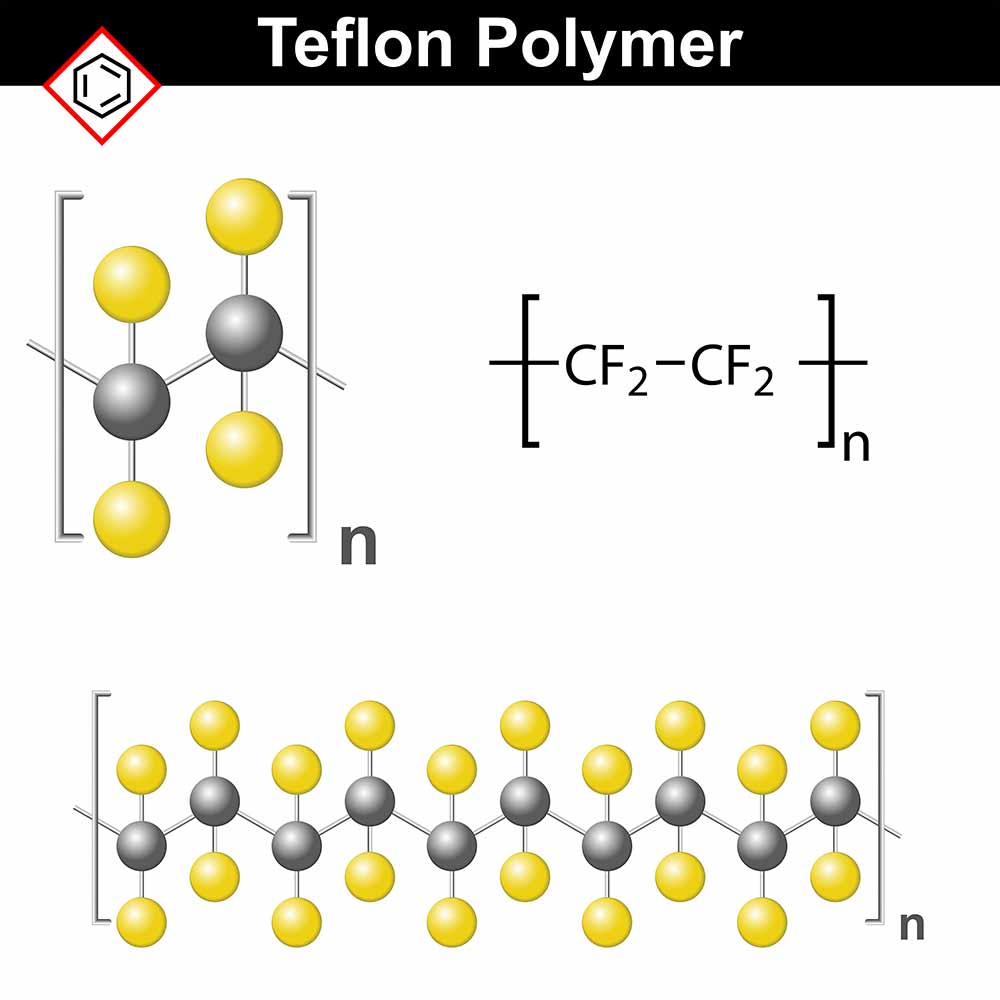
The structural chemical formula of Teflon material
These differences make PTFE better than FR4 when dealing with high-frequency signal transmission, including microwaves.
The material has a lower dissipation factor, stable dielectric constant against temperature changes, lower dispersion, and a lower coefficient of thermal expansion than FR4.
It is available with low-profile copper, as well.
However, PTFE is significantly more expensive than FR4, so you can design a hybrid PCB with both materials in the stack.
For instance, the inner layers can have FR4 to handle low-frequency signal transmission, while the outer layers can have PTFE to support microwave and RF signal line routing.
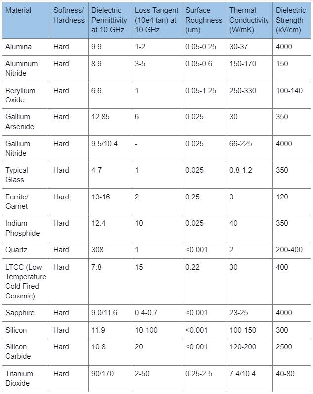
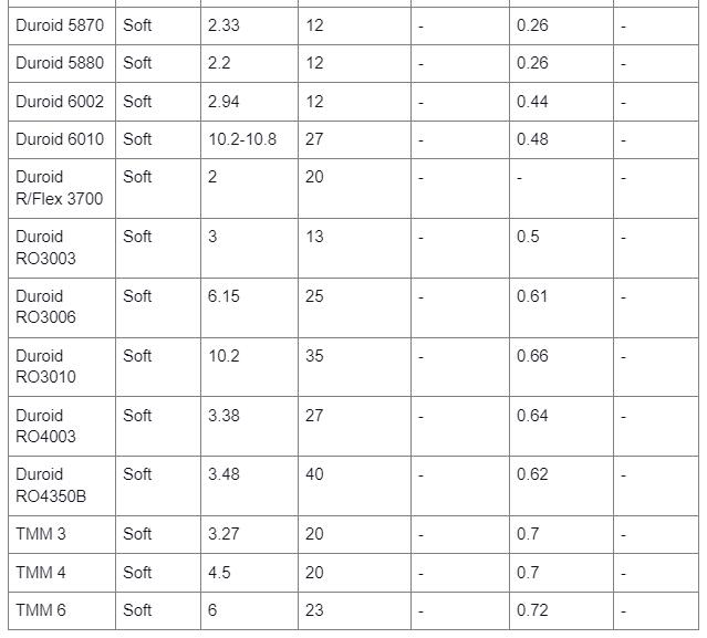
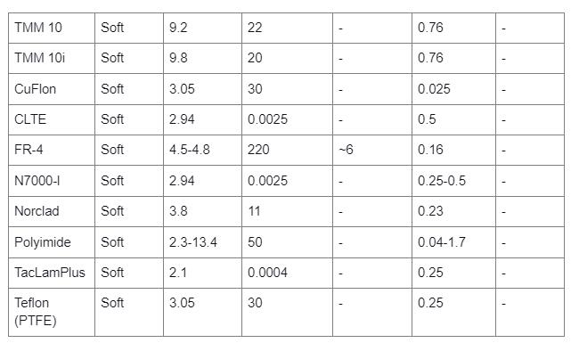
Common RF & Microwave PCB Materials’ Dielectric and Material Properties
How do RF and Microwave PCB Differ?
The most significant difference between the two is the radio frequency. Microwave PCBs fall under the category of over 2 GHz RF circuit boards. However, both are suitable for applications requiring transmission and receiving radio signals, specifically for dealing with networking signals.
Various RF circuit boards
Common Challenges and Solutions for RF and Microwave PCB Designs
Noise
High-frequency signals are highly sensitive to noise, which can be pink, white, or band-limited type. This noise can emerge from several sources, such as thermal agitation (thermal noise), shots from electrical current variations, short-term phase fluctuations, DC flicker noise, and diodes (avalanche noise).
A high-power radio PCB
You can cut off this noise by using band filters, which only allow a specific frequency range to pass through. However, this solution does not eliminate the source noise, the set of inaccurate signals within the frequency range that can pass through the filter. You can only eliminate this issue by separating the different parts and placing a ground layer under each RF/microwave layer.
Impedance Matching
High frequencies have a tight tolerance to impedance mismatching, so you should look into problems like the skin effect losses, which convert signal energy into heat. Proper impedance matching and gold plating can solve this issue.
You should keep the trace length short, as well. Long microwave and RF transmission lines have higher chances of experiencing signal loss. The ideal line length is 1/20 of the signal’s wavelength but if it must exceed 1/16 of the wavelength, you must use an inductor and capacitor (LC) for impedance control at the end of the line.
Return Loss
You can solve this issue by making the ground plane continuous from the driver to the receiver to keep the return signal from passing through other power planes.
Remember, normal return signals pass through the path of least resistance, but high-frequency return signals look for the path of least inductance, which is the ground plane under the signal layer. If this return signal passes through the power plane, it can cause heating, reflections, or ringing, causing significant noise.
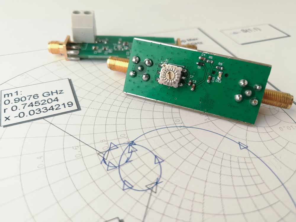
Microwave Circuit Board Material: An RF PCB placed on a Smith chart
RF/Microwave PCB vs. Normal PCB: Differences in Material, Design, and Manufacturing
Materials
Normal PCBs usually have FR4 substrates, but some can have polyimide base layers. However, the latter is more popular because it is affordable and provides good mechanical strength.
Although more expensive, polyimide has a higher temperature tolerance, better dimensional stability, and is less affected by high humidity levels.
But for RF applications, the most common material is PTFE because it minimizes signal losses and enhances the reliability of the high-frequency signal transmission in antennas, PCB transmission lines, and filters.
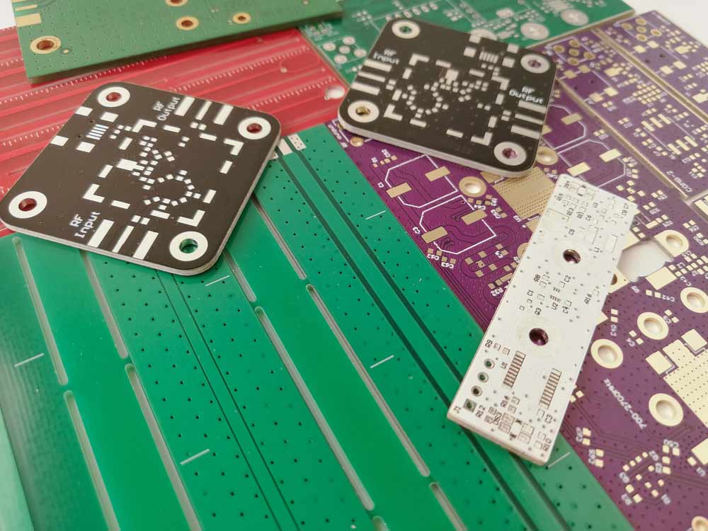
Microwave Circuit Board Material: Various multicolored PCBs for RF projects
Materials like Taconic, Rogers, Arlon, and low-dielectric-constant polyimide are also suitable. The most important factors here are low dielectric constants and low tangent losses.
Design
When designing a regular PCB, you don’t have to pay keen attention to factors like routing, impedance control, layout, and signal integrity. But with RF and microwave PCBs, you have to take care of signal transmission, impedance matching between signal sources, propagation, trace routing, and the layout to reduce signal interference and losses.
Manufacturing
After receiving the PCB design and layout, the manufacturing process for regular PCBs involves FR4 substrate creation, hole drilling, plating, component placement, soldering, testing, and quality control.
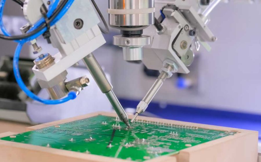
Microwave Circuit Board Material: Advanced high-precision robots in a fully automated PCB assembly line
But with RF and microwave PCBs, manufacturers have to select the most suitable material first, then take it through a specialized lamination process to add on the copper foil and dielectric/prepreg layers.
After that, the board undergoes high-precision processing to etch precise trace widths and drill tiny holes, followed by impedance control using coplanar waveguides, striplines, or microstrip transmission line structures. The last step is strict quality control using high-precision testing equipment to measure the signals and impedance.
OurPCB: Your Best RF/Microwave PCB Manufacturer in China
It takes quite a lot of work and precision to manufacture RF and microwave PCBs, so you should look for a reputable manufacturer to make these boards for your project.
At OurPCB, we pride ourselves in having broad expertise in handling RF/microwave circuit board fabrication because we’ve built such PCBs and achieved a high level of customer satisfaction.
We’ll help you save on costs as well by sending a prototype for testing, modification, and approval before going into mass production. Contact us today to get a free quote on your designs.
Summary
In conclusion, several microwave circuit board materials exist, each with different properties that suit specific applications. Considering the critical parameters described above, you should be able to pick the best material for your project.
If you think we left something out or have any questions or comments, leave a message, and we'll get back to you as soon as possible.
Special Offer: Get $100 off your order!
Please email [email protected] for details.