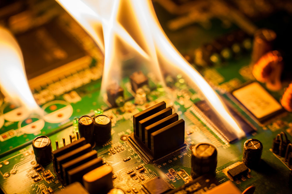
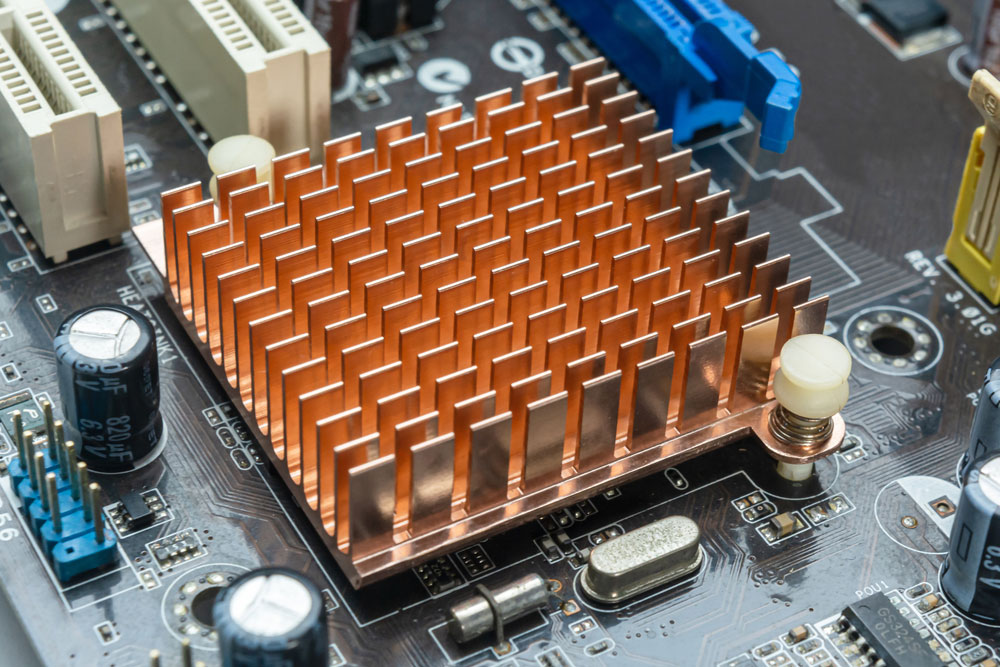
Some components and the resistance within the traces can generate heat in a circuit board. These high temperatures can cause damage if the PCB thermal resistance is high. You can use heat sinks or fans, but these are not enough. Additionally, they make the PCB bulkier, and fans increase power consumption.
The best solution is to develop a thermal management plan that accounts for the thermal resistance and conductivity. This strategy should keep the circuit board's highest temperature closer to the ambient temperature to ensure components operate optimally. We have looked at PCB thermal resistance and how you can improve your designs to maximize heat dissipation below.
Contents
- What Is PCB Thermal Resistance, and Why Is It Important?
- What Determines the Thermal Resistance of Your PCB Substrate?
- Methods of Measuring Thermal Resistance of PCBs
- Measuring Thermal Conductivity
- Guarded Hot Plate Method
- 3-Omega Method
- Bottom Line
- Design to Lower Thermal Resistance
- Use Materials with High Thermal Conductivity
- Place Copper Pads Under Hot Components
- Use Heavier Copper
- Supercharge Heat Dissipation with Alternative Substrate Materials
- Ceramic
- Metal Cores
- Tips to Manage PCB Thermal Resistance for Manufacturing
- Consider Temperature Coefficient When Selecting Components and PCB Substrates
- Give High Power Components Adequate Spacing
- Use Thermal Vias to Enhance Heat Dissipation
- Summary
What Is PCB Thermal Resistance, and Why Is It Important?
PCB thermal resistance is the inverse of the circuit board's thermal conductivity. It defines how fast/slow the PCB materials allow heat to move away from the source. In other words, it shows the heat transfer rate from hot to cold regions on the circuit board.
Two connections to the copper plane (thermal vias and thermal pad/thermal relief pads) impact thermal resistance.
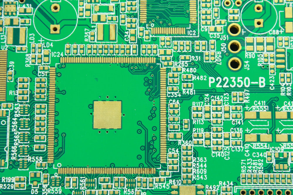
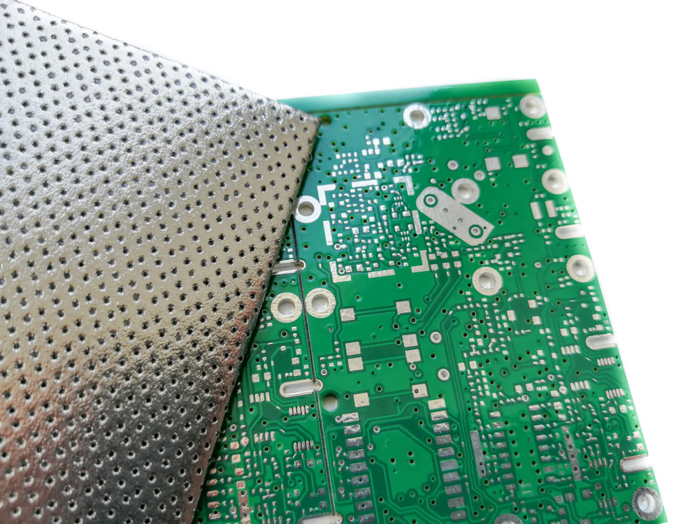
Vias in a PCB
Thermal vias dissipate heat from the components, while relief pads distribute heat evenly on the board during the soldering process.
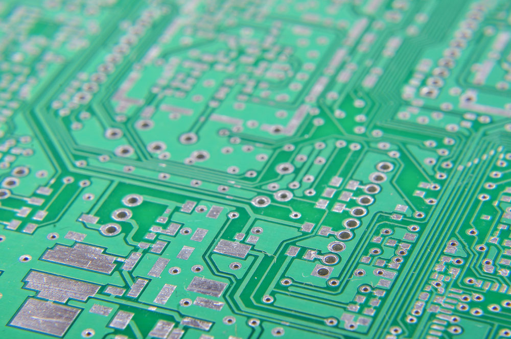
Several thermal pads on a PCB
Excessive heat accumulation in specific regions can cause fracturing of the high-aspect-ratio vias or active component failure.
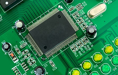
Component failure due to excessive heat accumulation
What Determines the Thermal Resistance of Your PCB Substrate?
The substrate's material properties and arrangement of conductors/copper elements in the PCB determine the thermal resistance. These two should assist in developing the thermal management strategy during board design.
The goal of the strategy is to reduce thermal resistance, and it should show the following:
- Best electronic component arrangement
- Which components need fans or cooling sinks
- Best thermal via placement near hot components
A cooling sink
Special Offer: Get $100 off your order!
Please email [email protected] for details.
Methods of Measuring Thermal Resistance of PCBs
There are three ways to measure thermal resistance.
Measuring Thermal Conductivity
The most typical method of measuring thermal resistance is by using thermal conductivity. Calculating thermal conductivity is a straightforward process, and resistance is the inverse of conductivity.
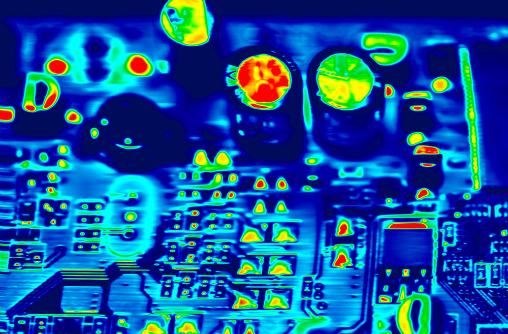
An infrared image of a PCB showing the hotspots
Guarded Hot Plate Method
Since circuit board substrates are two-dimensional, it is easier and faster to measure the thermal resistance of a complete but unassembled board using this method.
The process involves measuring the temperature of the two PCB sides as heat moves from the hot spots to other cooler areas. It is a direct way to measure thermal conductance, which you can use to calculate thermal conductivity and resistance.
3-Omega Method
This thermoelectric process involves heating the circuit board assembly using an AC heater at a specific frequency. The process creates a periodic heating effect at double the frequency.
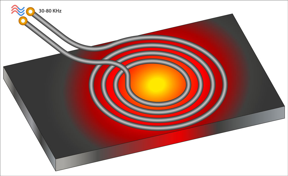
An alternating current heater
Measuring the temperature will indicate a signal containing components at the heating frequency and 3X the frequency, hence the 3-Omega name.
Thermal conductivity will be proportional to the power of the frequency components and the board's geometry. However, this method is only effective with small PCBs.
Bottom Line
As you might have noticed, all three methods directly lead to thermal conductivity. Therefore, you should use a PCB thermal resistance calculator to determine the thermal resistance because it takes in all the parameters required to calculate thermal conductivity, then gives the inverse.
Design to Lower Thermal Resistance
The following are the three ways to lower thermal resistance.
Use Materials with High Thermal Conductivity
The most effective way to reduce thermal resistance is to use materials with high thermal conductivity. Therefore, boards with hot components should have copper in plane layers to provide low-resistance, quick-heat flow paths. Alternatively, use the interior ground or power plane layers for high-frequency or high-speed boards. These will have multiple purposes because they also aid in isolation and provide shielding against EMI from the exterior.
Special purpose PCB shielding against electromagnetic interference
Place Copper Pads Under Hot Components
Positioning copper pads below hot components helps direct heat away from the surface layer. These pads usually have vias connected to the internal ground plane, and this plane image shields the components.
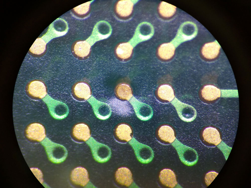
PCB pads and vias under a microscope
Some components feature a die-attached thermal paddle, and you should solder these parts directly to the thermal pad for maximum heat transfer. However, it is vital to note that placing too many or too large vias can allow the solder to pass through during board assembly.
Use Heavier Copper
Heavier or thicker copper traces can run higher currents with minimal resistance. Resistance causes the temperature to rise, so thicker copper will keep the temperatures low if the board must run at high power.
Supercharge Heat Dissipation with Alternative Substrate Materials
Another effective way of reducing thermal resistance is using alternative substrate materials. The typical substrate material is FR4. Its conductivity is significantly lower than metal and ceramic, at approximately 1.0 W/(m-K). This value is similar to the conductivity of other high-frequency compatible laminates like Isola and Rogers.
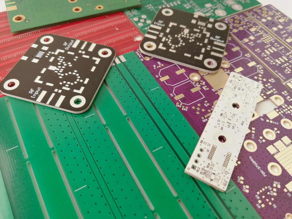
Several FR4 PCBs
However, metal and ceramic substrates have higher thermal conductivity, making them more attractive for thermal management.
Ceramic
The thermal conductivity of ceramic material ranges from 20-300 W/(m-K). Therefore, it is ideal for placing under or near hot electrical components. Additionally, it can eliminate the need for fans or bulky heat sinks.
Ceramics also has the advantage of having its thermal expansion coefficient closer to that of copper than FR4. Thus, it minimizes stress on thin copper traces and vias. However, the material is brittle and can fracture easily (FR4 is flexible).
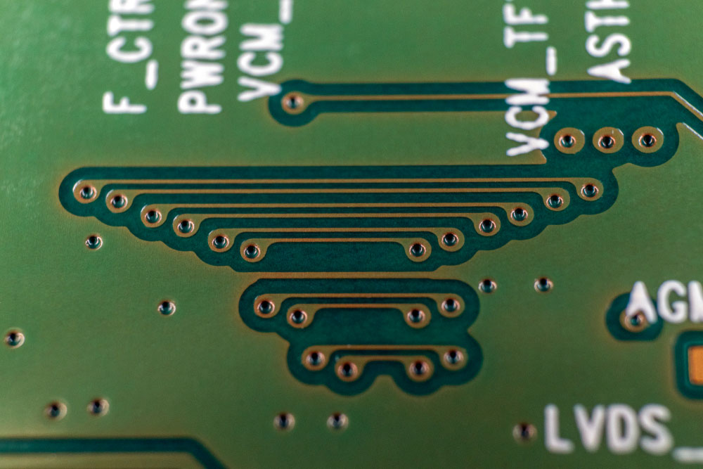
Non-stressed copper traces and vias on a PCB
Some ceramic materials include the following: boron nitride, aluminum oxide, silicon carbide, and aluminum nitride.
Metal Cores
usually have an aluminum metal sheet substrate with a 239 W/(m-K) thermal conductivity. You can connect the sheet to a nearby ground plane to create an extra EFI shielding layer. In addition to having better conductivity, the metal core provides better mechanical strength and flexibility than ceramic. High-power LED systems usually use metal-core PCBs because the diodes emit lots of heat.
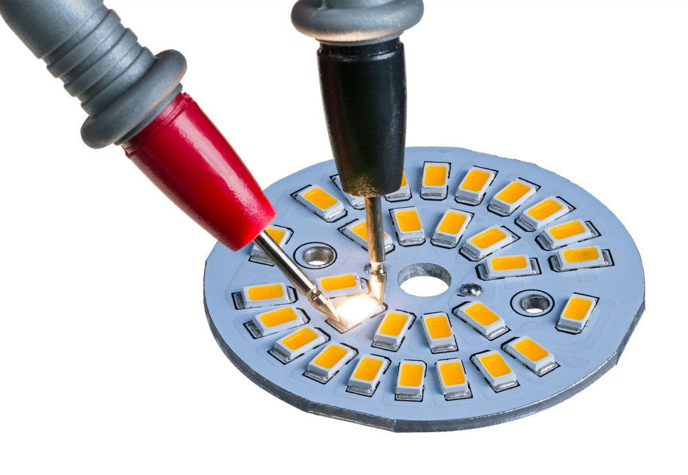
High-power LEDs on an aluminum PCB
Tips to Manage PCB Thermal Resistance for Manufacturing
Consider Temperature Coefficient When Selecting Components and PCB Substrates
As stated earlier, the board's material properties and components determine the component and trace thermal resistance. Therefore, you should select components and PCB substrates with favorable temperature and resistance parameters. For instance, aluminum is a better material than FR4 for quick heat transfer from LEDs.
Give High Power Components Adequate Spacing
Place heat-generating components sparsely on the board. This distribution should reduce hot spots, which can cause issues during assembly reflow.
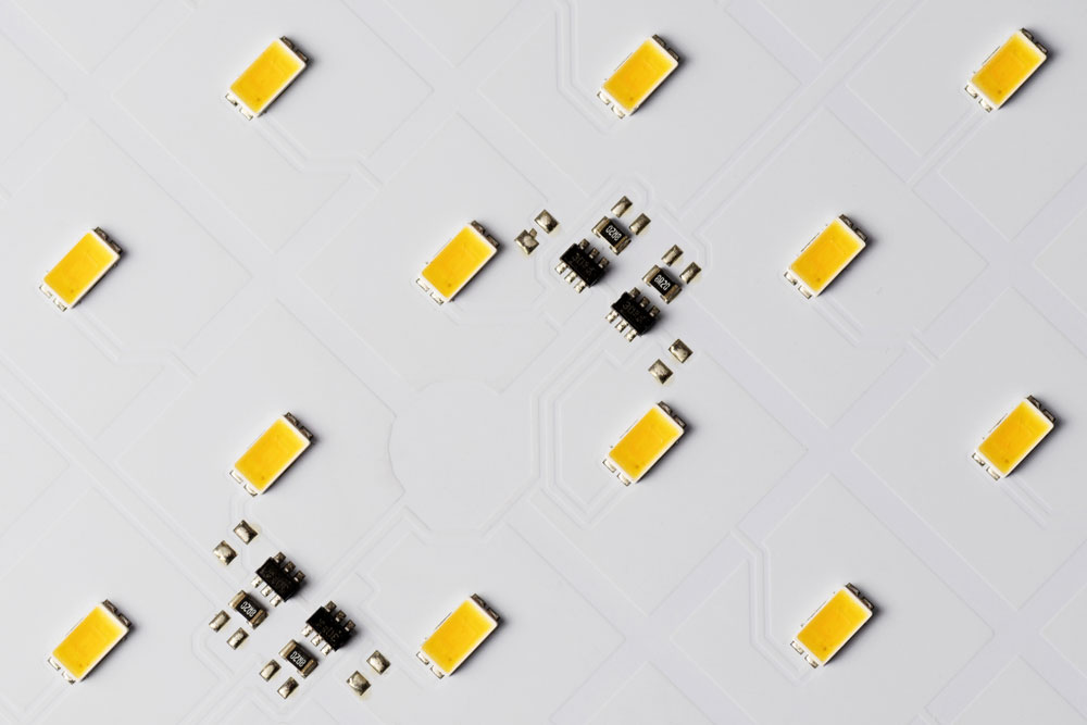
Well distributed high power LEDs on a white aluminum PCB
Use Thermal Vias to Enhance Heat Dissipation
Use multiple vias to evacuate heat from components, especially high-power SMD parts. Through-hole vias are better than buried, blind, and micro vias because they channel the heat out faster from the heat source, board surface, and components.
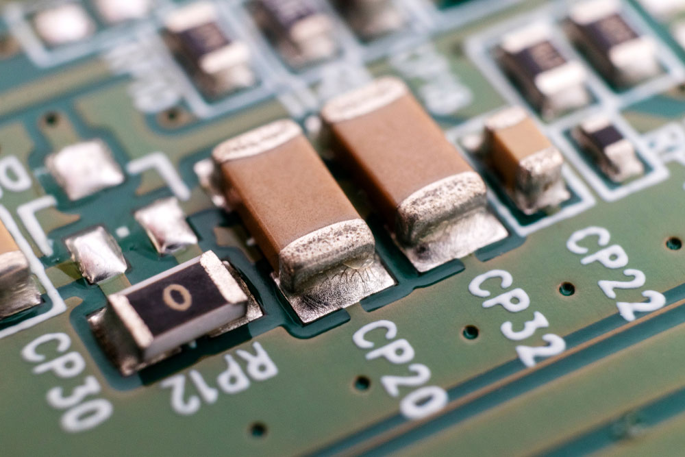
SMD components with vias closeby
Summary
In conclusion, it is critical to consider PCB thermal resistance during PCB design and manufacturing. Therefore, you should check several factors, such as the substrate material, vias, components, trace copper thickness, etc. We hope this article has been insightful, and if you have any questions or suggestions, contact us for more details.
Special Offer: Get $100 off your order!
Please email [email protected] for details.