LED PCB assembly - do you smell something burning? And then suddenly your LED light goes off? Or maybe the custom LED PCB doesn’t even light up when you supply power to the board?
Problems due to short circuit or open circuit of LED PCB components. These and many other issues can lead to LED PCB failure. It would help if you were careful about designing the custom LED PCB layout and when it comes to its PCB assembly.
Therefore, today, we will tell you about seven ways to avoid the failure of a custom LED circuit board.
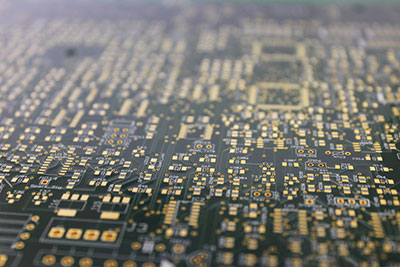
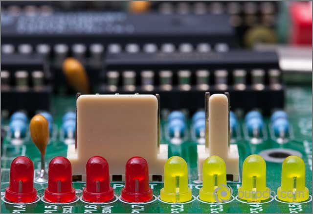
(Close-up of the printed, electronic circuit board with LED)
Contents
- 1.LED PCB Assembly May Experience Electrical Over Stress
- How:
- Prevention:
- You may use the current limiters and transient voltage suppression (TVS) diode.
- 2. Components May Shift On Custom LED PCB assembly
- How:
- Prevention:
- 3.LED PCB Assembly May Have Open Or Short Circuits
- How:
- Prevention:
- 4.Performance Degradation During The LED PCB Assembly
- How:
- Prevention:
- 5.Wrong PCB Design Of Custom LED PCB
- How:
- Prevention:
- 6. Industry Certification Of LED PCB Components
- How:
- Prevention:
- 7. Thermal Issues Of LED PCB Assembly
- How:
- Prevention:
- Conclusion:
1.LED PCB Assembly May Experience Electrical Over Stress
How:
The LED may undergo electrical overstress if you accidentally or deliberately operate it over its allowable electrical specifications.
Prevention:
You should ensure that you keep the following LED parameters below their maximum rated values: maximum voltage, maximum forward current, maximum reverse voltage or current, maximum surge current, maximum allowable temperature, and continuous pulse current. It will ensure that the LED PCB operates reliably, correctly, and robustly.
You may use the current limiters and transient voltage suppression (TVS) diode.
The TVS diode is a clamping device that you will need to connect in parallel to LEDs. During standard voltage, the TVS diode will turn off. But the diode will turn on when a voltage spike comes. After that, it will clamp it. It will protect your custom LED PCB.
On the contrary, you should connect the current limiter in series with the LED to be protected. It will limit the high current through the circuit and save the LED.
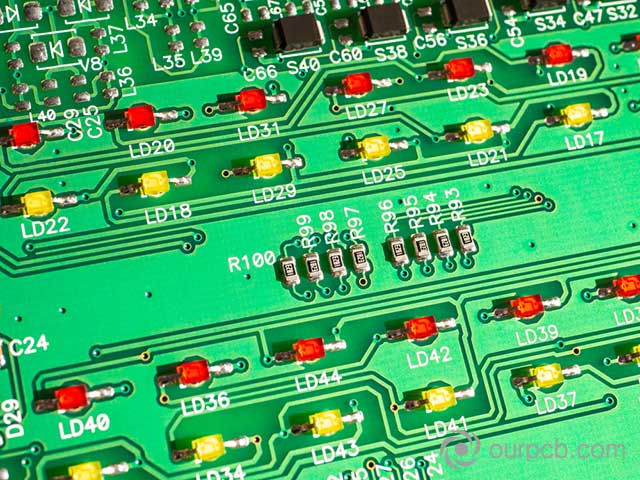
(It illustrates resistors which can limit the current through LED PCB assembly)
2. Components May Shift On Custom LED PCB assembly
How:
During PCB welding, some technical problems may cause LEDs to shift, eventually leading to failure.
Prevention:
It would help if you did not use limited solder paste while soldering. It will make it deteriorate quickly. Further, you should ensure that the solder paste is not expired. There is also a chance that the solder paste is not sticky enough to hold the LED PCB.
The PCB assemblers should ensure that they are not using excessive flux content in the solder paste. It may result in high solder flow when the LED PCB is going through the reflow machines. So, the components have a high chance of displacing from their original position. You should also handle the LED PCB assembly with care as mishandling. It can also cause failure.
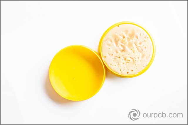
(Flux for LED PCB assembly)
3.LED PCB Assembly May Have Open Or Short Circuits
How:
If you inconsistently apply solder paste, it can lead to short or open circuits in the LED PCB. If you use it in limited quantity, the solder joints will be more prone to rupture. If you haphazardly use it in excess, it may connect with the nearby connections and cause short circuits.
In this case, you will burn not only the LED but also the sensitive nearby electrical components.
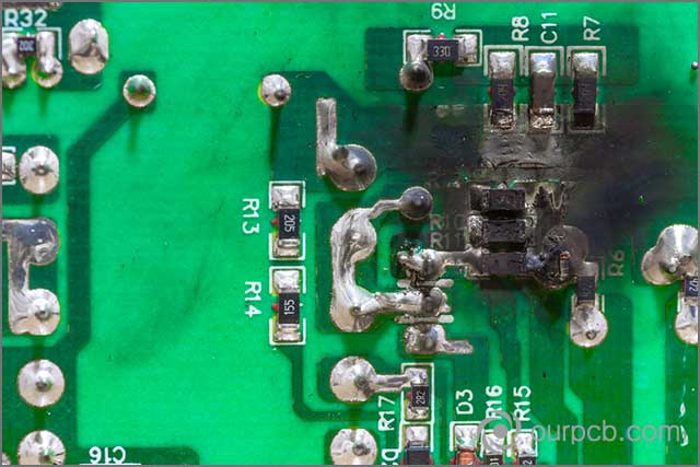
(It shows a heated LED PCB assembly due to short circuit)
Prevention:
You should make sure that the LED PCB does not get environmental contamination. It includes particulates or dust in the air, chemical spills, and skin oil after touching the PCB. Ask your PCB manufacturer to check for quality controls.
They should also ensure excellent in-house handling so that the LED PCB assembly remains undamaged and uncontaminated.
Furthermore, you may also use electrical testing to find the location of the short and open circuits. After that, you may contact the PCB manufacturer and ask them to do the complete root cause analysis.

(It shows an actual fire due to short circuit in the LED PCB assembly)
Special Offer: Get $100 off your order!
Please email [email protected] for details.
4.Performance Degradation During The LED PCB Assembly
How:
The LED PCB assembly may suffer from gradual performance degradation, and it is challenging to identify its root cause. However, we will list some common reasons and help you avoid them in the first place. Your custom LED PCB may be subject to trace degradation, oxidation, incorrect copper weight, condensation, and solder flux corrosion.
Prevention:
Prevention Trace degradation is often due to poor etching of the LED PCB assembly. You should avoid traditional print methods at home, such as using the Ferry Chloride etching solution. You should make sure that your PCB manufacturer is using the latest automatic machines for such purpose.
If you feel your LED PCB assembly is oxidized, it will be due to insufficient copper finishing. Your PCB manufacturer should provide your custom LED PCB with environmental protection.
Similarly, the LED PCB assembly may condense due to contact with moisture. This moisture might diffuse into the PCB assembly during its fabrication or while it was under storage.
(It shows a dirty and poor PCB assembly)
The LED PCB assembly will have incorrect copper weight if you don’t have proper PCB design skills. You may somehow define improper trace size and width, which will eventually lead to the failure of your custom LED PCB. The solder flux corrosion can be due to flux residue during the assembly of your custom LED PCB. Therefore, you can avoid it by solder mask, aerosol spray coatings, and epoxy coatings.
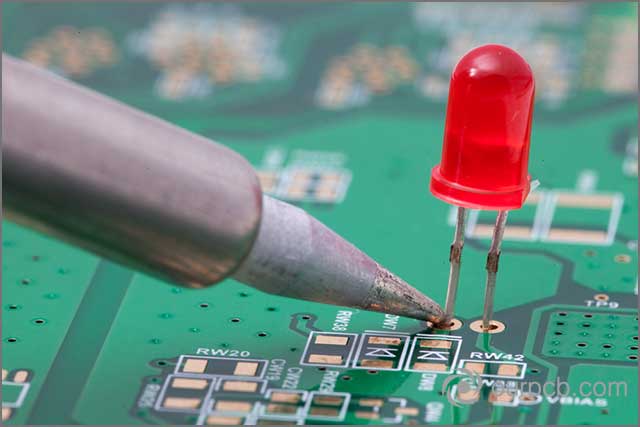
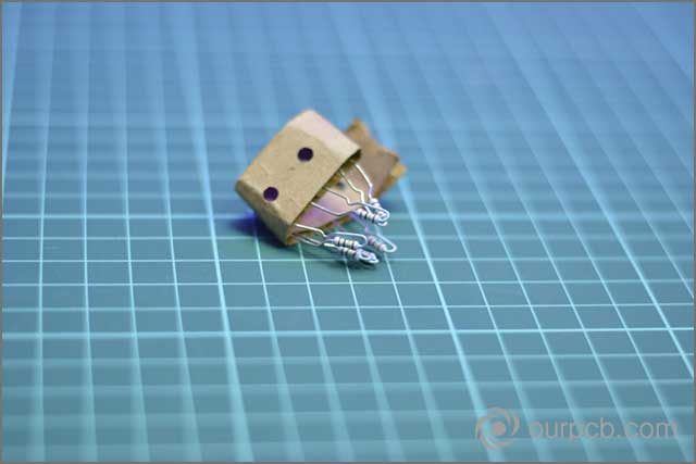
(Carefully solder the custom LED PCB)
5.Wrong PCB Design Of Custom LED PCB
How:
If you have lousy PCB designing skills, you can cause the failure of your LED PCB assembly. Because you may incorrectly place the components, there may be less area on PCB, which may cause component overheating, or there may be a power failure.
Prevention:
First of all, you should keep an appropriate creepage distance from the copper pads and the edges of other metal parts connected to the housing. These creepage distances include trace-to-trace, pad-to-trace, and pad-to-pad spacing.
Usually, it is a good practice to keep an 8-mm creepage distance among primary and secondary circuits. And, to keep a creepage distance of 4-mm among primary channels and ground. Secondly, you should make sure that there is an insulating medium between the two metals.
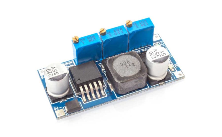
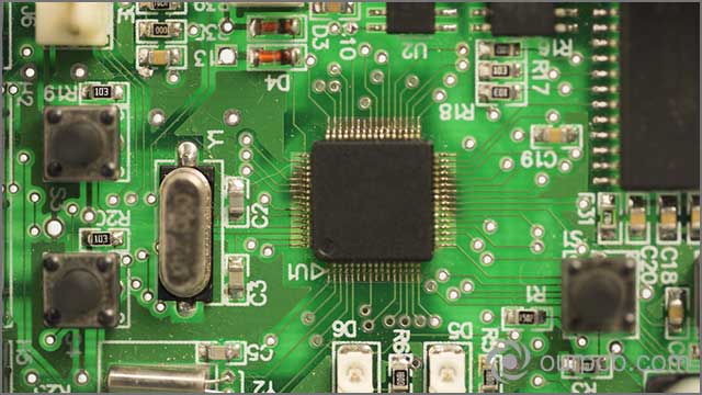
 (An example of good LED PCB assembly design)
6. Industry Certification Of LED PCB Components
How:
It is very critical that the PCB manufacturers must adhere to industrial regulation and protection standards. If they would not follow them correctly, your LED PCB assemblies may fail.
Prevention:
The PCB manufacturers must pay careful attention to the quality and comply with industrial standards at all PCB manufacturing phases. This way, they will be able to produce reliable, safe, and high-performing LED PCB assemblies.
There are industry regulations and protection levels available for almost every production phase of PCBs. The firms would need to understand the three classes of products generally defined by industrial standards. They should know when to use dedicated service electronic products, general electronic products, and high-performance electronic products. They should perform all the acceptance tests to ensure high-quality.

(Check all the standards for good quality of LED PCB assembly)
7. Thermal Issues Of LED PCB Assembly
How:
LEDs, diodes, and other electronic components in the LED PCB may produce heat while functioning. If they provide extreme hear, it can damage them or affect their performance. Therefore, this is another cause of the failure of custom LED PCB.
Prevention:
So, how can you ensure better heat transfer and dissipation in the LED PCB assembly? There must be some supplemental cooling to maintain their temperature within their safe, defined limits. One way is to use a heat sink in your LED PCB design. It will prevent overheating of any electronic devices.
Heat sinks are optimized and designed to allow the electronic components to operate within the safe limits. In the same way, you can also use a heat-conducting tube and connect it with the element generating high heat. It will provide a path for heat transfer.
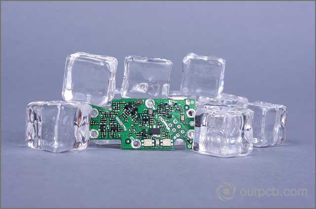
(It shows thermal management idea of LED PCB assembly)
Conclusion:
By following the above-suggested methods, you will significantly reduce the possibility of circuit board failure. However, unless you work with a manufacturer with the capabilities and expertise to produce high-quality circuit boards and have established quality processes to accomplish this task, the right design decisions are not enough.
To help you get started the best way, we will begin by carefully reviewing the files for you. If you are ready to make a design, or if you want to learn more about PCB, please contact us.
Special Offer: Get $100 off your order!
Please email [email protected] for details.