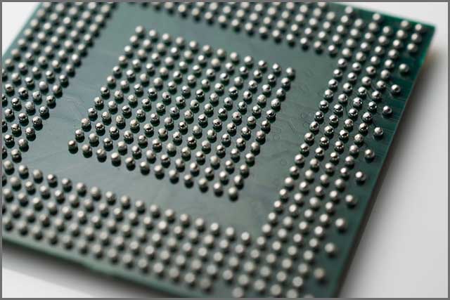
A solder ball is a glob of solder that connects a chip package and a PCB.
You can also use solder boards to connect stacked boxes in multichip panels.
They can be mounted on circuitry boards manually or through automated equipment.
Their placement is usually secured through a tacky flux.
Solder balls are also the most common defect that detracts from SMT assembly processes.
However, solder balls are a double-edged sword. A solder ball placed within 0.13mm of traces or wider than 0.13mm in diameter violates the principle of minimum electrical clearance.
The errors that can cause a solder ball to bring about defects in an assembled PCB are innumerable.
According to IPC, solder balls do not cause defects long as they're held firmly in place. This article examines the good, the bad, and the ugly of solder balls.
Contents
- 1、What is a Solder Ball?
- When Solder Balls are Bad News for PCB
- 2、Solder Ball--Solder Ball Valve
- How to Solder a Ball Valve
- 3、Solder Ball--How to Make a Solder Ball?
- 4、What Causes Solder Balls During Hand Soldering?
- Moisture
- Solder Ball--Circuit board
- Smeared Stencils
- Solder Ball--Inappropriate Solder Paste Formulation
- The Best Troubleshooting Technique For Solder Balls that Occur During Hand Soldering
- 5、The Solder Ball Joint Reliability
- 6、Problems and Defects
- Solder Ball--Wave soldering
- Exploding Volatile Materials
- Solder Ball--In Summary
- The Best Troubleshooting Methods
- 7、Solder Ball--Conclusion
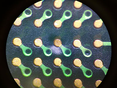
1、What is a Solder Ball?
Solder balls are also called solder bumps or spheres due to their geometry.
A solder ball is a spherical piece of soldering used to connect chip packages to PCB.
Solder balls are created through sequential flow/quench or reflow processes.
After passing through these processes, they're then degreased and classified.
You can increase a solder ball's contact reliability by flattening its ball shape into a coin shape.
We call such a solder ball a coin solder ball.
When Solder Balls are Bad News for PCB
A solder ball can also cause defects in a PCB. They can undermine the electrical reliability of a PCB electronic.
Solder balls within 0.13mm of traces or a diameter wider than 0.13mm violate the principle of minimum electrical clearance.
The IPC A 610 standard stipulates that even solder boards
 Solder Ball
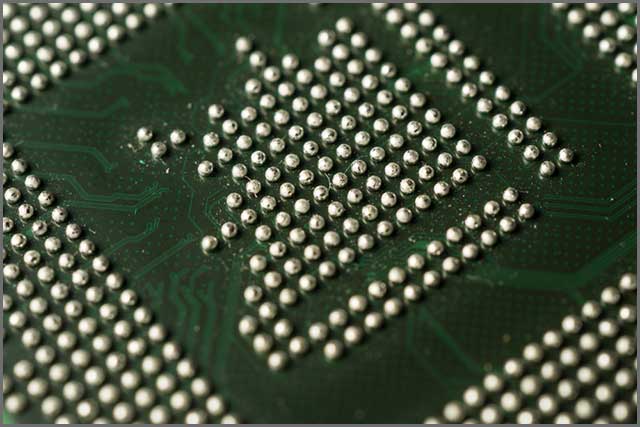
2、Solder Ball--Solder Ball Valve
A solder ball valve can connect between multiple chip stacks in a PCB.
It can regulate the flow of electrons and signals between the various layers of the pile.
Solder ball valves are usually in a Ball Grid Array (BGA).
A BGA usually provides more interconnectivity than a dual in-line or flat package.
How to Solder a Ball Valve
The method described here involves placing solder ball valves on BGA packages using a ball pickup tool.
The primary objective is to form an array of solder balls on a substrate.
You'll use this substrate to interconnect the conductive sites on other substrates.
To implement this method, you'll need a ball pickup tool.
This ball pickup tool uses vacuum suction to pick up solder balls from a fluidized ball reservoir.
That implies you need a solder ball reservoir containing a collection of premade solder balls.
The reservoir should also come with attachment agents.
That also implies that you need at least one vacuum.
That also means that you need at least one vacuum source to provide the orifice of the tool with suction power.
The vacuum suction tool has at least one orifice for picking up a premade solder tool.
It also comes with a controllable ball seat connected to a vacuum source and a pressure source.
The tool deploys a jet of gas to inject the picked solder balls into the conductive sites of a substrate.
In another technology arrangement, the substrate pads are placed in a fluidized ball reservoir.
The coating is applied with a flux or adhesive that attracts and binds with the solder balls in the pool.
Still want to learn more about the best ways to use solder balls? You'll find that out in the next chapter.
 Solder Ball
Special Offer: Get $100 off your order!
Please email [email protected] for details.
3、Solder Ball--How to Make a Solder Ball?
One of the oldest and most widely used solder ball creation methods is the 3-Orifice design.
In this method, you first acquire a solid solder alloy, preferably an Sn63Pb37 or a Lead-free solder.
Craft the solder alloy into a solder wire or a solder sheet.
Cut the wire into tiny pieces for a wire, and knock out specks for a solder sheet.
Cut out pieces and bits in measures that will accurately yield the volume of a solder ball with a 2mm diameter.
Next, place the pieces and specks into a column of hot oil to melt.
The upper section of the column of hot crude should have a temperature above the melting point.
Moreover, the lower section's temperature should be below the melting point.
You'll obtain your desired solder balls when the pieces and specks in the column of hot oil melt.
Next, cool the balls in a viscous liquid.
Note that the presence of oxides in the column can distort the spherical shape of the balls. However, you can place a flux film over the column to prevent this.
This method is highly efficient and low-cost.
With this method, you can create up to 7,000 high-quality solder balls per second in any orifice.
However, the technique also comes with its downsides.
The technique can be fraught with contamination and turn out messy.
Each ball will have a different weight, although you can measure their values.
Also, it's nearly impossible to obtain balls with a tolerance of 1.5%.
The Importance of The Packaging on The Formed Solder Ball
As noted above, the presence of oxides can distort the shape of the solder ball.
One way to prevent the oxidation of the solder balls is through packaging.
Not only can packaging prevent the removal of oxygen, but it can also prolong the shelf-life of the solder balls even beyond their expiry date.
Want to learn more about how to avoid defective solder boards? The next chapter holds the answers.
 Solder Ball
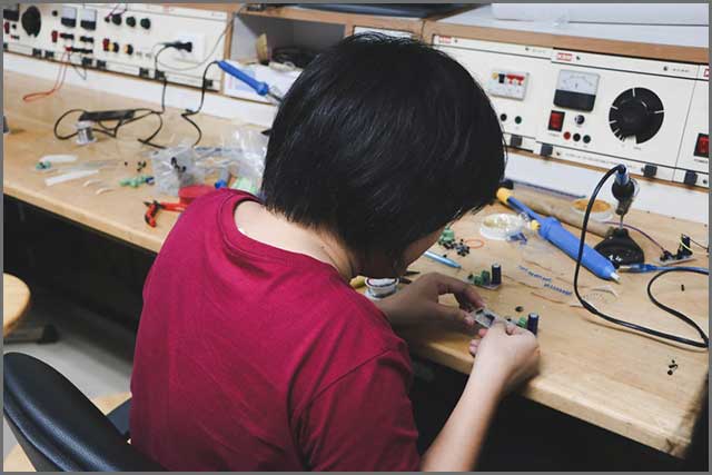
4、What Causes Solder Balls During Hand Soldering?
Here are some of the causes of solder balls.
Moisture
Moisture in your solder paste can cause solder balls to explode during reflow.
Water seeps into the solder paste during refrigeration.
If the paste does not attain room temperature after removing it from the refrigerator, it will soak up moisture.
However, you can eliminate the water by baking.
Solder Ball--Circuit board
The board itself can bring about undesired solder balls during hand soldering.
Air, moisture, or alcohol used to clean the board can yield unwanted solder balls.
These contaminants can creep in between layers, open vias, and through holes in a board with cracked or incomplete plating.
Moreover, these contaminants are forced out when the board undergoes heating in reflow.
Their abrupt escape shoots gases in all directions and blows liquid solder across the board.
Paste flux gases may also produce this effect when they escape from the panel sections close to the surface.
There isn't much hope if your board admits contaminants through open edges, vias cracks, and through holes.
You'll likely need to remake the board, as you can't bake the trapped air away.
If paste gasses are jetting off from underneath the board, you can resolve this by reducing the amount of paste.
You can also fix this by minimizing the paste's volatiles.
Smeared Stencils
Your stencil might be depositing solder paste discriminately.
You need to ensure that your under-stencil cleaning process is efficient and thorough.
It could be that you're using an inappropriate under-stencil wiping roll, which is too thick.
The improper thickness of the registration can cause the balls to spread across the underside of the stencil.
Moreover, when you eventually use the stencil on a PCB, the extra balls get deposited on the board.
Solder Ball--Inappropriate Solder Paste Formulation
Poorly formulated solder pastes may explode during heat reflow and blow liquid solders randomly across the board.
The volatile materials are usually the most likely cause of the explosion.
In such cases, you can prevent such explosions by reducing the preheat ramp rate.
That allows the volatile material to be pushed out without abrupt outgassing.
However, you need to ensure that you preheat slowly enough.
The Best Troubleshooting Technique For Solder Balls that Occur During Hand Soldering
The best way to determine the causes of solder balls during hand soldering is to test multiple products.
The aim is to check to see if the defect occurs in certain types of PCB.
Run various boards with the same solder paste and equipment to pinpoint the exact variables the fault originated.
In the next chapter, we will delve into the reliability of solder balls and what troubleshooting techniques to use.
 Solder Ball
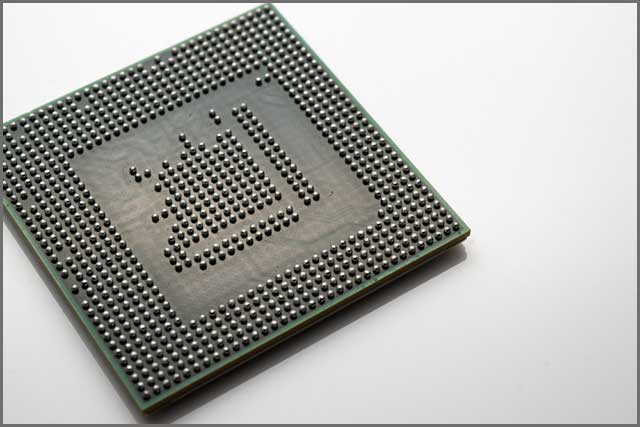
5、The Solder Ball Joint Reliability
Studies have been conducted to show the effects of Pd film thickness on the solder ball joint reliability.
The survey subject was electroless Ni/Pd/Au plating on an Sn-3.0Ag-0.5Cu (SAC305) solder ball joint.
The study used a solder ball shear test.
After multiple reflow cycles, the Pd film thickness between 0.05-0.02 microns was the optimum for solder joint reliability.
Studies have also shown that solder ball joints are more reliable when using 0.02-micron-thick electrodes.
This result is even better than that obtained using electroless Ni/ Au plating.
The study also shows that the shape and thickness of the intermetallic compounds (IMCs) determine a solder ball's reliability.
In particular, the degree of adhesion at the dendrite layer of the IMCs/solder interface immensely influenced a solder ball's reliability.
It was also shown that (Cu, Ni, Pd)6Sn5 IMCs containing minute Pd yield excellent solder ball joint reliability mainly because Pd inhibited the growth of IMC.
Want to explore further the issues that limit the reliability of the solder balls? Read on
6、Problems and Defects
The IPC A 610 standard stipulates that five solder balls with diameters
Solder Ball--Wave soldering
Random solder balls can occur due to spitting from the wave. This defect is therefore linked directly to the wave soldering parameters. The separation of the lock can be attended by the placement of the solder in the distance away from the tracks.
In such an instance, the solder may bounce back off the bath.
Also, a solder ball may result if you incorrectly set the preheat or increase the flux quantity inappropriately.
In this case, the solvent will escape from the flux defectively.
You can identify this problem by hovering a glass plate above the wave.
You should see some bubbles at the bottom of the glass as the glass contacts the wave. The fewer bubbles you spot, the better.
You also need to confirm that the resist and flux are compatible.
Exploding Volatile Materials
The occurrence of random solder joints can also be caused by explosions caused by the volatile residues in the flux.
You can resolve this by placing a piece of the white card above the wave, leaving it there while it runs.
It would help if you did not process the board while doing this the first time.
Afterward, run the board through the machine while the piece of the white card remains in place.
You'll most likely identify the culprit from there.
Solder Ball--In Summary
Many reasons can cause defective solder boards. Below is a rundown of the most common causes:
The lack of solder masks between adjacent pads.
The preheat temperature isn't high enough to activate the flux.
The lack of adequate space between adjacent pads.
Improper placement of elements on a circuit board.
Solder residues left behind on PCB surfaces and pads.
Solder paste squeezed out due to too high pressure from placement.
The use of paste in excesses and the occurrence of paste slump.
An unclean stencil smeared with solder paste on its underside.
Misalignment of solder paste during printing.
The Best Troubleshooting Methods
1. Make sure the mat and template are compatible and the dimensions are right.
2. Cleaning the stencils as quickly and as thoroughly as possible.
3. Adjust the solder paste printing pressure.
4. Eliminating the gap between the PCB and the stencil.
5. Using another solder mask between the pads.
6. Adjust the pressure to pick and place the nozzle.
7. Separating the new flex from the old flex.
 Solder Ball
7、Solder Ball--Conclusion
One way to ensure you get things right is to use high-grade observation tools.
Check up on any place a solder paste is used during every process using a microscope or x-ray.
Regardless of the type of installed components and the PCB or whether to clean the panel, you can use these tools to observe.
However, by doing so and using the information in this guide, you'll make the best use of solder boards.
Not all the representatives from your manufacturer are knowledgeable enough concerning the peculiarities of your PCB electronics.
Nonetheless, you should be able to get assistance from your manufacturer.
However, you need also to ensure that the technical assistance you're getting from your manufacturer comes from a seasoned technician.
However, we have a solid track record and a full breadth of experience with solder balls and PCBs.
You can tap into our in-depth knowledge reservoir of SMT processes today.
Special Offer: Get $100 off your order!
Please email [email protected] for details.