But you can't' jump at any Zener diode you find. First, you have to know the bias condition of the device. Thus, you need to use the basic testing procedure to confirm if it's open, sound, or shorted. Also, you need to understand all the complex codes inscribed on the device.
And the best way to know this is by using a Zener diode tester.
So, do you want to learn more about this subject?
Let's' get to work!
Contents
How Does the Zener Diode Work?
First off, a Zener diode works as a constant voltage device. And it has a limited dynamic resistance internally. So, when a voltage drop occurs, there will be a slight variation of the active resistance with the current. Hence, it's' vital to quote the Zener voltage ranges at a specific draft (5 – 10mA).
Also, you can measure the current that flows through the Zener diode by getting the resistor's value. And the difference between the battery voltage and Zener voltage.
Thus, if you have a high voltage Zener, you should expect a lower voltage different than the low Zener voltage. As a result, you may have a measurement error.
Another remarkable feature of the Zener diode is that the device works like a standard diode.
The only difference is that the Zener diode is reverse biased when the current moves backward. But when the current flows forward, the Zener is forward biased. In other words, this device has a predictable voltage drop.
Special Offer: Get $100 off your order!
Please email [email protected] for details.
Two Ways You Can Measure the Zener Diode Voltage
You can measure the Zener diode voltage by using the following methods:
Using a Multimeter's' Ohmmeter
You can start by putting the positive probe on the diode's anode. Then, the new investigation will go to the diode's cathode. You can take the resistance readings (which should be relatively low).
Cathode-Anode Diode Resistance Test

Cathode-Anode Diagram
Source: Wikimedia Commons
You have to do the reverse of the former process at this stage. That is, your ohmmeter's negative probe of the multimeter should be on the diode's anode. Then, place the positive probe on the diode's cathode. Consequently, you should have a higher resistance. Also, the multimeter may show "OL" for an open circuit because the opposition is high.
So, your diode is in good condition if you have a low resistance with the first process and high resistance with the second. An open diode will show high resistance in both procedures. But you'll' have low resistances in both setups when you have a shorted diode.
Using a Multimeter’s Voltmeter

Multimeter Voltmeter
Source: Maxipixel.net
In this procedure, you can either use a voltmeter directly or a multimeter voltmeter. And you can proceed by feeding your Zener diode with maximum voltage.
While you're at it, the voltage has to be reverse bias with a resistor in series. Also, your rated Zener voltage has to be lower than the voltage. In addition, ensure that the voltage measurement across the Zener diode is close to the rated Zener voltage. A suitable voltage will read a voltage near its rated Zener voltage.
As for an open diode, you'll' see a higher voltage reading near the voltage supply. And the shorted diode will have a lower voltage reading than its rated voltage.
Zener Diode Tester Circuit
The components you need for this circuit are:
- Battery – 1.5V (4)
- LED 1 – 5mm red
- S2 – SPST push switch (N/O)
- R1, R4 – 1K
- U1 – NE555N IC
- S2 – SPST toggle switch (N/O)
- R2 – 10K
- DVM – three-wire
- R3 – 2K7
- C4 – 470µF/25V
- C3 – 100µF/63V
- Q1 – P55NF0 Power MOSFET
- L1 – 10µH Inductor (200mA)
- D1, D3 – 1N5819 Schottky Diode (40V)
- C2 – 10nF
- D2 – 1N4752 Zener Diode (33V)
- C1 – 1nF
Note that the resistors are (1/4 Watts).
This setup is a simple dc-dc boost converter. And the design is around the 555 chip.
You can wire the U1 (555 IC) as an astable oscillator. That is, you can wire it at a frequency of about 68KHz. The frequency determines the RC components (C1, R2, R1).
Then, the NE55N IC's' output drives the power MOSFET directly. And it switches the current via the power inductor. Further, the C3 and D1 create the filter circuit and output rectifier. But if you want more efficiency, swap the D1 with a fast diode (UF4001).
At this stage, the D2 (Zener diode) will put the output voltage close to 33V. Also, the R3 (ballast resistor) helps limit test current via the device you're testing.
How Does the Zener Tester Circuit Work?
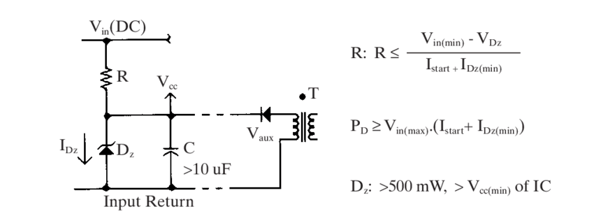
Zener Tester Circuit Diagram
Source: Wikimedia Commons
The Zener receives a constant known currently from the Zener tester. Then, there will be different Zener currents. And the values will help you plot a characteristic curve of Zener voltage vs. current.
So, one of the transistors (T2) will draw some current if the emitter voltage goes high base-emitterT2's' base-emitter knee voltage. Consequently, it will reduce the first transistor's base voltage (T1). Hence, the emitter voltage will decrease as well. But if the T1's' emitter Ofallon continues to fall below the T2's' base-emitter voltage, T2 will draw less current.
As a result, the collector voltage will increase with the T1's' emitter voltage. Also, due to the negative feedback system, you'll' see a value of about 0.6V for the constant voltage.
So, if your setup has about three switches and two closes, the current will move to the resistors (R1 to R3). Then, the multimeter that connects to the setup measures the Zener voltage. In the process, you have to join a high resistance. Consequently, only a slight current will draw from the Zener.
Interestingly, it's' possible to adjust your circuit if you want a high voltage Zener measurement. And you can achieve this by using a high voltage T1 (transistor). While you're at it, ensure that your T1's' dissipation doesn't' surpass high current ranges.
FAQs
How do you find the voltage of a Zener diode?
Then, measure the diode's stage across. You can do this by placing a multimeter lead on each terminal. Get your multimeter and put it on the DC voltage setting. With this, you should see a value that ranges from about 5.6V to 5.88V. Also, your weight may be as low as 5.32. But your voltage will remain 9V between the battery and ground.
How do I test if a diode is working?
It's' ideal for testing your diode when it's' forward biased. In this state, you can measure the voltage drop across. Also, a forward-biased diode behaves like a closed switch. Hence, it will let the current flow. In addition, you can use the resistance mode. But it isn't so accurate.
Do Zener diodes go bad?
Of course, yes. Your Zener can go wrong. MosThis often pens when there's surplus power dissipation across the device. That is, manufacturers produce Zener diodes with specified rated power dissipation. So, when the power dissipation across the device exceeds the diode's rating, it fails.
Rounding Up
Special Offer: Get $100 off your order!
Please email [email protected] for details.