It's crucial to understand essential electronic components—especially when you plan to invent an electronic project. With this, you can detect features in good and bad conditions—an electronic circuit troubleshooting skill. In other words, if you want the best results, you need to do a diode test and ensure that other essential components, like the LED, resistors, etc., are in good condition. That way, you won't have issues assembling the ingredients in a PCB.
But, if you decide to assemble things before confirming the state of the components, it may be difficult to spot the problem.
Luckily, we'll focus on the diode test in this article.
Let's dive in!
Contents
Special Offer: Get $100 off your order!
Please email [email protected] for details.
What Is a Diode Test?
A diode is a simple two-pin device with a built-in electric field that conducts electric current in one direction. And the diode comes from semiconductor materials.
The device has different applications, like separating signals from a supply, converting AC to DC, etc. The diode has two sides you can dope differently—the n-side and the p-side.
Therefore, electrons skip the junction when applying a positive charge to the p-side and a negative account to the n-side. At this point, the current moves in only one direction.
With that in mind, it's vital to note that the significant property of diodes is: that conventional current only flows from the positive to the opposing side. Also, electrons can move from the negative to the positive side—in only a single direction.
So, how do you perform a diode test? You can start by detecting the terminals of the device (cathode and anode). The cathode is the airport close to the band, while the anode is on the opposite side.
For instance, the cathode of a Zener Diode is the terminal near the black mark.
You can test with different techniques like the analog multimeter, digital Multimeter, etc.—which we'll discuss later in this article.
What if you want to test a diode you assembled on your PCB? You can still use the methods here by detaching one lead of the diode.
How Do You Test a Diode Using a Digital Multimeter?
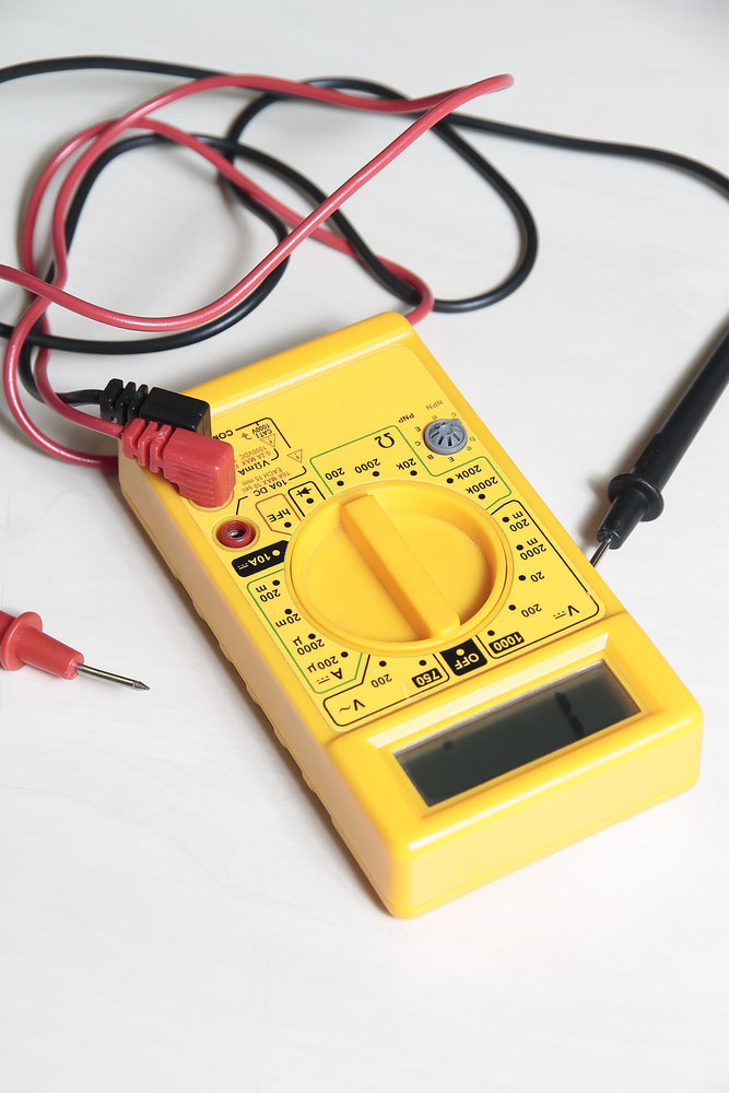
A digital multimeter used for testing diode
When it comes to performing a diode test with the Digital Multimeter, there are two modes you can use:
1. Resistance Mode
The Resistance Mode measures two things: the reverse and forward bias resistance of the diode.
So, if your diode is in excellent condition, you should see about a few Kilo Ohms of the forward bias resistance and a very high reverse bias resistance. And if it's terrible, the meter will show a low value (a few tens of Ohms).
Steps
- A. Once you find your diode's cathode and anode terminals, ensure that your Digital Multimeter is in resistance or ohmmeter mode. You can turn the middle knob to the resistor values or ohm symbol.
While at it, confirm that the selector is in low resistance mode (about 1K Ohm) for the forward bias. Also, the reverse bias testing should be in a high resistance mode (100K Ohm).
- Attach the black probe to the cathode and the red probe to the anode. This way, the diode is forward-biased.
- Then, change the terminals of the Multimeter. That is the cathode to the red probe and the anode to the black examination. Hence, you'll have a reverse bias.
So, you have an open diode if the meter shows a high OL or resistance in reverse and forward bias. But if you have low resistance for both conditions—you have a short diode.
2. Diode Mode
On the other hand, the Diode Mode is a better testing mode because it depends on its features. This mode involves placing your diode in the forward bias.
When this happens, the Multimeter measures the voltage drop across the diode. Hence, if your diode is healthy, it will let current move the forward bias and cause a voltage drop.
Steps
- Once you find your diode's cathode and anode terminals, ensure that your Digital Multimeter is in diode checking mode. You can do this by turning the middle knob till it gets to the diode symbol. Interestingly, the Multimeter can offer a current of about 2mA between the test leads in this mode.
- B. Place the black probe on the cathode and the red examination on the anode. With this, you have a forward bias diode.
- Pay attention to the readings. So, it's healthy if you see a Silicon Diode voltage value between 0.6 to 0.7. Also, if it's a Germanium Diode, the voltage value should range from 0.25 to 0.3.
- Reverse the terminals. That is, put the black probe to the anode and black to the cathode. With this, you'll have a reverse bias. And in this condition, the current doesn't flow through the diode. So, for a healthy diode, your meter should read OL or 1.
If you have a bad diode, your meter will show irrelevant values. If you have an open diode, no current will flow through it in both conditions. So, your meter will show OL or 1.
But if the diode is short, the current will flow through it because it's acting like a closed switch. Hence, your meter will read between 0V to 0.4V.
How Do You Test a Diode With an Analog Multimeter?
Testing a diode with the Analog Multimeter is similar to the ohmmeter mode of the Digital Multimeter. And this is because this device doesn't have a dedicated Diode Test Mode.
Steps
- Ensure that you place your multimeter switch in low resistance value.
- Attach the negative terminal to the cathode and favorable to the anode—to have a forward bias condition. If the meter displays a low resistance value, your diode is healthy.
- Proceed to reverse the terminal. That is the cathode's positive terminal and the anode's negative terminal. Then, ensure that your selector is in the high resistance position. With this, you have a reverse bias condition.
Also, it's important to note that this procedure applies to simple PN diode testing. An ideal diode will show a high resistance or OL on the meter. But a lousy diode will display a low resistance.
Special Offer: Get $100 off your order!
Please email [email protected] for details.
How to Test a Zener Diode
You'll need more circuitry than simple PN diode testing to test a Zener Diode. And it's because you have to apply a reverse voltage more significant than the Zener breakdown voltage—to get a reverse bias condition.
Steps
- When you find the terminals of the Zener diode, attach a test circuit.
- B. Then, put your multimeter knob in voltage mode.
- Proceed to attach the meter probes across the Zener diode.
- Afterward, boost your input supply to your diode. While you're at it, monitor the Voltage that the meter shows. If you have a healthy Zener diode, your meter reading should increase as the variable supply rises.
So, this will continue until the breakdown voltage of the diode. Also, if it goes beyond this point on your meter, you should see a constant voltage value—regardless of a rise in input variable supply.
For instance, if you add a 10V to the Zener Diode alongside a 5V breakdown voltage through a resistor from the battery—your meter reading should be approximately 6V. So, if you have this, your Zener diode is healthy.
How to Test LED (Light Emitting Diode)
It's pretty easy to spot LED terminals. The short term is the cathode, while the longer one is the anode. With this in mind, you can test the LED with a DMM.
Steps
- Ensure that your multimeter knob is in diode mode.
- Attach the probes to the LED meter. If the LED is healthy, you'll notice a glow. With this, you should have a forward bias. And the LED doesn't work in a reverse bias condition. Hence, reverse bias testing isn't possible.
What Causes a Diode to Fail?
A diode could fail due to some of the following conditions:
- Voltage Breakdown—is when the electrodes (positive and negative) have a path between them, and the resistance (forward and reverse) becomes infinite.
- Reverse Voltage—occurs when the reverse resistance decreases, which affects unidirectional conductivity.
- Performance Degradation—this is when the circuit's stability declines.
- Open Circuit— it happens when electrodes of the diode disengage. Plus, the reverse and forward resistance become infinite.
- Forward Voltage happens when the resistance (forward) is enormous, increasing the voltage drop and reducing the output signal.
How Do You Know that a Diode is Blown?
You can start by turning the multimeter knob to diode mode. If your diode is blown, you'll notice that the diode symbol will resemble a triangle facing a line.
Final Words
Doing a diode test isn't rocket science, after all. But first, you must identify the type of diode you're using. Then, spot the terminals and connect them accordingly. Afterward, take note of the readings that your DMM or Analog Multimeter produces.
What are your thoughts about doing a diode test? Do you have suggestions or questions about the topic? Please feel free to contact us.
Special Offer: Get $100 off your order!
Please email [email protected] for details.