A motor controller is a bridge between the microcontroller in your robot, motors, and batteries. It is a crucial part of the mechanics because a single motor controller has the power to provide around 0.1 Amps of current.
If you compare this to DC or servo motors, they need much higher current to work. Selecting a motor control for your machine does not have to be complicated. Read the following guide to understand the matters needing attention.
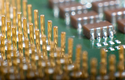
 (Motor controller PCB model diagram)
Contents
- 1.Types of Motor Controllers
- a. Electronic Units
- b.Electromechanical Units
- 2. Direction Controller Through H Bridge
- 3.Speed Controller Through Pulse Width Modulation
- 4.Armature Controller Through Variable Resistance
- 5. Turning Off the Motor
- 6.Motor Controller Selection Criterion
- a. Electrical Specification
- b.Operating Specification
- c.Features
- 7.Motor Braking
- 8.Motor Controller Applications
- 1. Multi-Axis Controllers
- 2. Robotic Motion Controllers
- 3. Servo Amplifiers
- 4. Inverter Drives
- 5. Microcontroller
- 6. Silicon Controlled Rectifiers
- 7. Digital Signal Processors
- 8. Pulse Width Modulation
- Conclusion
Special Offer: Get $100 off your order!
Please email [email protected] for details.
1.Types of Motor Controllers
a. Electronic Units
These units are super high-tech and have superior features. You get oscillating frequency drives or soft start with this kind of motor control. You can also design them to send a response to the inputs of a system, and create a pre-requisite condition for running the machine.
b.Electromechanical Units
These units utilize electromagnetic contractors. They can start, halt, change the way the motor is functioning.
2. Direction Controller Through H Bridge
If you need a process to control a DC motor, this is one of the most straightforward solutions. There are two pairs of switches. When you connect any of these pairs, they create a complete circuit and generate power.
If you are planning on making a four sectional motor, you can do so by mixing and matching these switches or changing their polarities. You can find them easily in some microprocessor-based controller or as chips. You can change the size of this H Bridge to fit smaller systems. Another possible application for this is controlling speed.
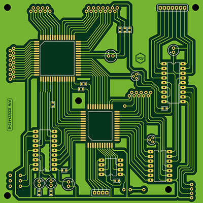
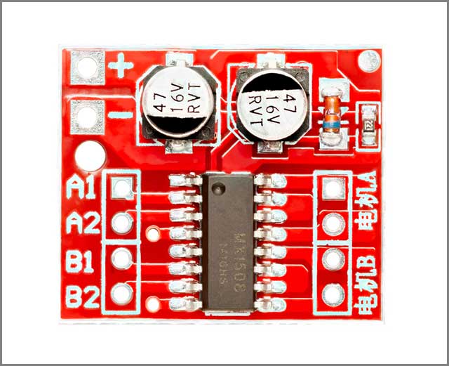 (Dual Channel H-Bridge DC Motor Controller)
3.Speed Controller Through Pulse Width Modulation
PWM circuits can determine the velocity of the motor by limiting or boosting the PCB supply voltage. When you take into account the smoothing effect they have through coil induction, it makes it seem like the motor is being powered by a voltage which is higher or lower than the actual voltage.
You can combine them with H bridges to change direction, velocity, and manipulate braking.
Special Offer: Get $100 off your order!
Please email [email protected] for details.
4.Armature Controller Through Variable Resistance
The third way of changing the speed of DC motors is to change the currency that is running through the armature or the coil. Shaft speed varies depending on the supply current because it is proportional to the magnetic field generated by the current in the armature.
If you want to limit the speed, you can add resistors to the armature coil. You can introduce a stator resistance to bump it up.
This method can be somewhat inefficient depending on the factor that when you add a resistor, you are losing energy and generating heat, which is why this is not a highly preferred method.
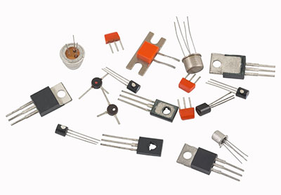
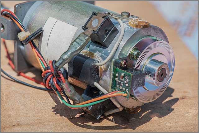 (Brushless DC motor with Controller Parts and PCB)
5. Turning Off the Motor
You can do this by cutting off the PCB voltage supply. The alternative is opening the switches that are in the motor. The thing to remember here is that, at a time, you can only switch on two switches that are connected side by side.
By closing 1 and 3, you are sending a positive sign from wither sides, and the ground signal has nowhere to go. It will put the motor control into a break mode. The direction of the motor depends on the inputs send to it, and also which switches you are manipulating.
6.Motor Controller Selection Criterion
a. Electrical Specification
1. Maximum Output Voltage
It is the output of the device, which should comply with the output of the system.
2. Rated Power
The highest power level that the motor can use.
3. AC/DC Supply Voltage
The range of AC/DC input voltage for flawless operation.
4. Continuous Output Current
The current device will usually carry without exceeding the heat limitation.
5. Communication Standards
Serial and Parallel interfaces are some considerations for this, including some examples like CANopen, AS-I, etc.
6. Bus Types
Consists of advanced technology attachment, industry-standard architecture, etc.
7. Single/Three Phase Inputs
We can use low pressure/high-pressure applications.
8. Peak Current Output
The maximum possible current output for a short period.
9. Motor Controllers
They use a frequency between 50 to 400 Hz.
10. Computer-Based Motor Controllers
They utilize various types of communication and buses.
b.Operating Specification
How you design the setup and control system will determine how the motor control performs. You can add various kinds of manual controls like jumpers, knobs, potentiometers. On the other hand, you can also use computer controls such as a digital pane, PCMCIA slots, joystick, etc.
1. The control programs are kept inside storage that is stale and detachable.
2. You can design any handheld device that can work through a remote.
3. The motor control can have different styles of mounting such as panel, chassis, DIN rail, wall, PCB.
c.Features
These controllers are flexibly chosen based on the functions you want to include in the PCB controller.
Motor speed controllers come with various feature options. Soft start will allow you to determine how long you wish to take for the device to power up. Critical for systems that are under heavy load or require careful handling. You don’t want to drown them in high current at the same time.
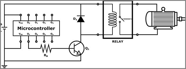
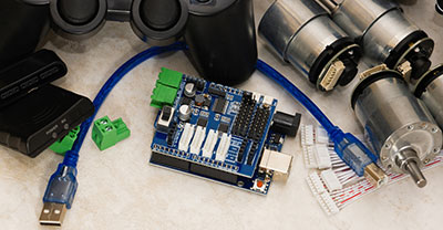
(Relay and Transistor interfacing a connection between microcontroller and a DC motor.)
7.Motor Braking
In dynamic braking, the method used is to remove the power supply from the motor. In dynamic braking, the method used is to remove the power supply from the motor.
Injection breaking is only available for AC motor control. When the power is disconnected, and instead you are supplying DC power, a magnetic field is created, which slows down or halts the motor by turning the direction of motor rotation.
Regenerative braking operates similarly to dynamic. You remove the power source and send back to the supply through the rotating motor. It can charge the battery, which then supplies that current to the machine.
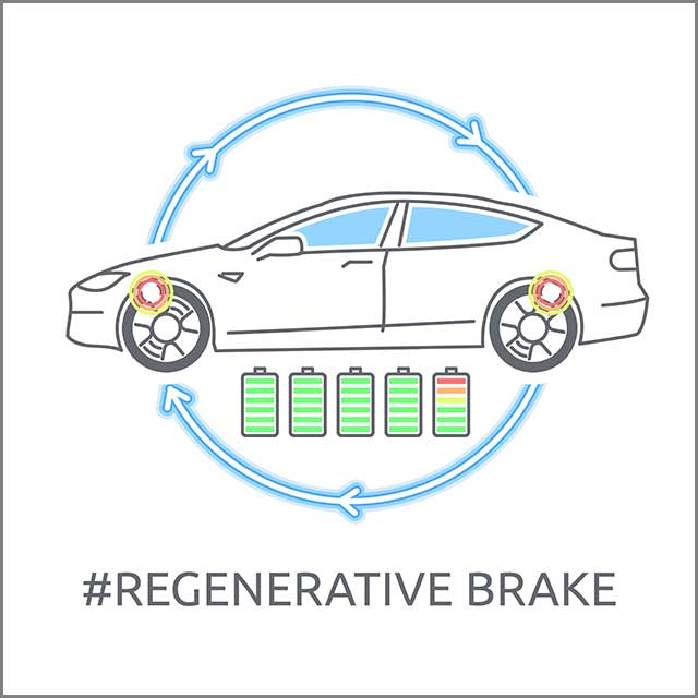 (Electric car regenerative brake charging.)
Break output is a kind of switch that can send a relay to control a break.
Auxiliary input/output are responsible for handling response from the system or handling communications.
Status monitoring works through alarms, which sets off when there is a change in a parameter. When you have a faulty system, which can be caused by excessive voltage current or speed, or change in temperature, the operator will be alerted.
Self-configuration is known as auto-tuning, which determines in real-time, what is the operating parameters needed to work at optimum capacity.
An electric car designed for a variety of applications, they can have an alarm, a speedometer signal, etc.
The self-diagnosing motor speed controller can determine the problems that are causing the system to malfunction. Then report the fault to the operator.
8.Motor Controller Applications
1. Multi-Axis Controllers
They determine the motion requirements, control, and surveil them.
2. Robotic Motion Controllers
They have software and hardware that can be used in robotic systems or applications.
3. Servo Amplifiers
They serve to generate a small degree of analogue signals which can create higher power or current
4. Inverter Drives
We need to convert the AC power input to DC power.
5. Microcontroller
They are the system placed on a chip, which can help control the flow of digital data that can change the operating conditions of the chip.
6. Silicon Controlled Rectifiers
They are used in conjunction with DC motors and can fine-tune the AC to generate DC.
7. Digital Signal Processors
Microprocessors are in charge of manipulating data in real-time. It includes the audiovisuals, heat, pressure, location, and then manipulate them through various controls. When you need motor control to be high resolution, you can use multiple special parts that can re-program the chip.
8. Pulse Width Modulation
It is called scalar control. They can convert AC frequency and voltage into DC, which operates on a sine curve. If you place a high torque work, these drives are not very good at low speeds, since they are individually controllable.
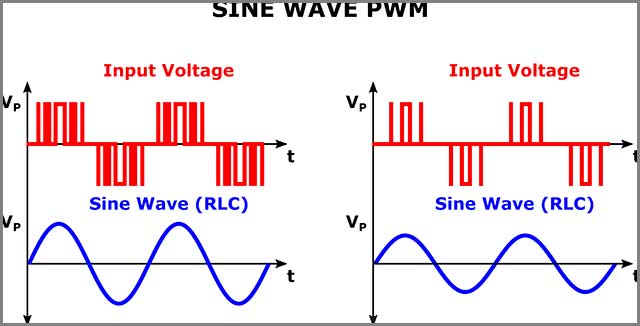 (Recreating a sine wave with a PWM)
Conclusion
This article has raised some of the most common issues encountered when selecting a motor controller. You need to take a closer look at the motor drives you need, as they will determine which power requirements you can use.
After this, you can choose the features described above, depending on your needs. The functionalities of the controller can be diverse, and depending on the controls, you might need expert help in determining the right controller for your setup.
We will provide the motor controller and PCB related services. You can send files to our mailbox. OurPCB has more than ten years of PCB manufacturing experience and can provide you with high-quality PCB manufacturing services to help you complete projects more efficiently.
Special Offer: Get $100 off your order!
Please email [email protected] for details.