Voltage surges caused by spikes, lightning strikes, and radio frequency broadcasts in the power supply volts usually affect electrical devices. Electronic equipment, including transformers, PCBs, and microcontrollers, are susceptible to voltage surges. Technologists solved the problem by introducing opto-isolator circuit in devices.
Their purpose was to prevent disruptions in various pieces of equipment, like guitar amplifiers. Optocouplers provide a risk-free method for making low-voltage electronics and high-voltage components function proportionately alongside one another.
Let's now dive deeper into the basics of optocouplers.
Contents
- What is Opto-Isolator?
- Opto-isolator Basic Construction
- Different opto-coupler Types
- Simple and basic Opto-coupler
- Special optical coupling
- Home-made Opto-coupler
- Opto-coupler Transfer Ratios
- Parameters and Specifications for the Opto-Isolators
- Opto-isolator Pros and Cons
- Opto-coupler usage notes
- Optocoupled SSRS
- Opto-coupled TRIACS and SCRS
- TRIAC interfacing
- Analog interfacing
- Digital interfacing
- Application
- Conclusion
Special Offer: Get $100 off your order!
Please email [email protected] for details.
What is Opto-Isolator?
An opto-isolator (an optical isolator, photocoupler, or optocoupler) is an electronic device that uses light to transmit electrical signals between two separate circuits. Additionally, they protect signal-receiving systems from high voltages.
(opto-isolator)
Opto-isolator Basic Construction
Common electronic components of an opto-isolator are a power supply, a closed channel, a photo sensor (often a photodarlington transistor, phototransistor, or photodiode), and an IR LED.
Generally, manufacturers package the two parts in a housing resembling a transistor with additional leads or an Integrated Circuit. Moreover, they encase the components in an opaque shell to minimize interference from ambient light.
Opto-isolators have several subcategories determined by the kind of light-sensitive component used and the design choices. The two most frequent types are:
Phototransistor: This light sensor makes use of the phototransistor in its construction.
Photodiode: Uses silicon photodiodes as detectors and LEDs as light sources.
(photodiode)
Different opto-coupler Types
The common types of Opto consist of the following;
Simple and basic Opto-coupler
An optocoupler is self-contained, sealed equipment with two separate optical (light) Rx and Tx components. They have separate power sources, but both have an optical linkage.
The Rx unit may be an option-triac, photo-FET, phototransistor, or another photosensitive semiconductor element, while the TX unit is a LED. Manufacturers place Tx and Rx components together in a sealed and single container.
Special optical coupling
Slotted optocoupler
The slotted optocoupler's first option has a slot between the phototransistor light sensor and LED light source. Typically, light may flow from LED to transistor-1 (Q1) with no severe reduction by the Opto slot.
However, inserting an opaque item inside the slot may fully obstruct the optocoupler. Thus, you may use the slotted optocoupler in several 'presence'-detecting applications, such as detection of liquid levels, limit switching, and end-of-tape detection.
Reflective optocoupler
Then, we have the reflective optocoupler that transmits electrical signals. In this case, manufacturers optically split the Q1 and LED inside the packaging to point outwards from the device. A reflecting item (like tape) is positioned externally on the package according to the Q1, and LED may provide an opto-coupled connection.
The reflecting optocoupler has several potential uses, including but not limited to: fog/smoke detection, measuring/counting engine-shaft revolutions, tape-position sensing, etc.
Home-made Opto-coupler
It is possible to build a simple optocoupler at home from scratch. As such, inserting a phototransistor and LED into a heat-shrinkable tubing or hard plastic tube yields the desired effect.
With this DIY optocoupler, you can adjust the length of the tubing to fit your needs. Moreover, you can even bend it to fit in tight spaces. A reflective inner tubing would naturally be more effective than plain black tubing.
Special Offer: Get $100 off your order!
Please email [email protected] for details.
Opto-coupler Transfer Ratios
Technologists spectrally match the phototransistor and LED (which normally function in the IR region) to enhance opto-coupling efficiency.
The simplest approach to define the efficiency of an Opto-coupling is to cite its output-to-input current transfer ratio (CTR). Ideally, CTR (IC/IF) is the ratio of the phototransistor's output collector current (IC) to the LED's forward current (IF). You can express CTR as a percentage, like 50%, or a single number, like 0.5.
Usually, basic isolating optocouplers featuring output stages from single transistors exhibit average CTR values ranging from 20% - 100%. The exact CTR figures depend on the device's output and input currents and the phototransistor's supply voltage (VC).
Note; The individual optocoupler CTR values may differ from the average value due to variances in the current gains of a phototransistor and LED radiation efficiency. Thus, any optocoupler with an average CTR near 60% may have a real value between 30% - 90%.
Parameters and Specifications for the Opto-Isolators
The following are some other critical criteria and specs for optocouplers;
- Bandwidth; It is the highest frequency at which a signal passes through the optocoupler when functioning normally. Depending on the architecture of the gadget, typical values might range from 20 kHz to 500 kHz.
- IFMAX; It's the maximum DC you can freely supply in an input LED. In addition, the standard ranges are between 40 mA and 100 mA.
- VCEMAX; Maximum DC voltage over output transistor with 20V-80V as the typical range.
- Isolation voltage; It is the maximum DC voltage between output and input circuits. 500V to 4kV is the typical range.
- Linearity
Opto-isolator Pros and Cons
Opto-isolators, like any other electric device, have their pros and cons.
- Advantages
The following are some of the many benefits of opto-isolators:
- First, they provide both physical and electrical isolation of two different portions of a circuit and, therefore, wholly protect the circuit.
- Secondly, they can minimize electromagnetic interference (EMI) and noise susceptibility and lower interferences like electrical interference.
- Also, they are low in cost and modest in size.
- They can additionally restrict voltage across several circuits.
- Lastly, they can provide isolation in circuits.
- Disadvantages
The limitations include the following;
- Some electrical systems can't utilize them.
- Then, factors like barometric pressure, air pollution, and humidity affect circuit arcing and isolation. It is, therefore, better to use the device in climate-controlled spaces.
- Opto-coupler working principle
An Opto-transistor DC Switch
- In our circuit example, an external 270k resistor regulates the phototransistor's base region sensitivity. The resistor's value depends on the switching sensitivity and photo-coupler device.
- The capacitor prevents accidental Opto-transistor base triggers from transients or spikes.
- Opto-Triac isolators can detect data and DC signals and operate the mains lamp and AC equipment.
- Opto-coupled triacs like the MOC 3020 have 100mA maximum current and 400-volt ratings, making them excellent for direct mains connection.
- Then, the Opto-Triac may feed the gate pulse to a bigger triac through a current-limiting resistor in high-powered loads.
Opto-coupler usage notes
Optocouplers are straightforward to use. Here, the output acts as a phototransistor, while the input acts as an LED. The following are some usage notes.
Optocoupled SSRS
Optocoupled solid-state relays (SSR) can replace low-power electromechanical relays. It offers complete electrical isolation between its output and input circuits. Its output is a switch with a low resistance when closed but near-infinite resistance when open. When closed, it passes DC or AC currents relatively easily, with no 'offset voltage' losses.
Opto-coupled TRIACS and SCRS
The semiconductor power-switching devices, triacs, and silicon-controlled rectifiers (SCRs) are photosensitive, similar to transistors. Simply put, an optocoupled SCR /optocoupled triac is just a LED, and SCR/Triac is combined into a single chip.
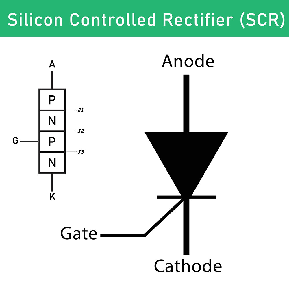
(Silicon-controlled rectifier)
You can operate the input LED like a regular LED, then use the triac/SCR as a low-power Triac/SCR.
The components are also widely available in both basic and complicated varieties. For example, some modern Triac kinds have zero-crossing switching and interference-suppressing circuitry in their package.
TRIAC interfacing
Appropriate use for the triac interfacing optocoupler is coupling the low-voltage control circuit's output (possibly by grounding one side of its power supply) to a triac power-control circuit's input. It receives an AC power supply and drives motors, heaters, and lamps.
It effectively functions when you use 115V AC instead of 230V. Also, you must select the actual Triac type and ensure it meets supply/load/supply needs.
Analog interfacing
An optocoupler may use LED to modulate the standing current, linking analog signals from one circuit to another.
Digital interfacing
Optocouplers can digitally interface applications with diverse output and input power supplies. They may interface digital computers output to lamps, relays, and motors; different IC families; digital ICs of the same family (CMOS, TTL, etc.). Then, you can achieve the interface using traditional or digital optocouplers.
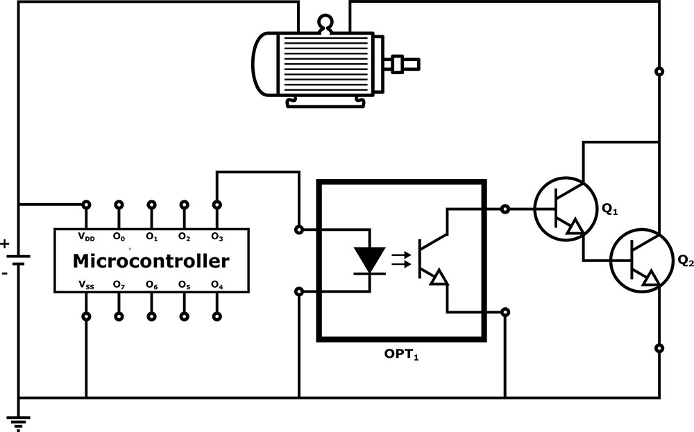
(Circuit diagram of the microcontroller using optocoupler)
Application
The applications comprise the following;
- Electrical noise isolation and electrical power,
- Signal isolation,
- High voltage level shifting,
- Isolating ground loop currents,
- Industrial and medical applications, and
- Power supply feedback systems.
(optocouplers in a circuit)
Conclusion
All in all, an opto-isolator exchanges an electrical signal using light between separated circuits. The electronic component work in monitoring and communications systems that utilize electrical isolation to effectively limit emitters from impacting low-power circuits.
For more information, kindly contact us.
Special Offer: Get $100 off your order!
Please email [email protected] for details.