 If you’ve been to the mechanic to fix a persistent problem that throws a dashboard light, you must have seen an OBD-II scanner in use.
But have you ever wondered how that port ended up in your car or how it works? Let’s look at how OBD works and its advancement over the years.
Contents
Special Offer: Get $100 off your order!
Please email [email protected] for details.
What Is OBD?
OBD is an acronym for On-Board Diagnostics, a computer system built originally to increase fuel economy and reduce carbon emissions by monitoring primary engine components in road vehicles.
Vehicle manufacturers and engineers developed this system in the 80s to respond to these three primary factors.
- Emissions Control: OBD systems monitor engine components to check for failure or underperforming parts that can increase engine emissions.
- EFI: Car manufacturers intensified the production of cars with electronic fuel injection engines in the 80s, a system that requires computer control to pump fuel into the engine
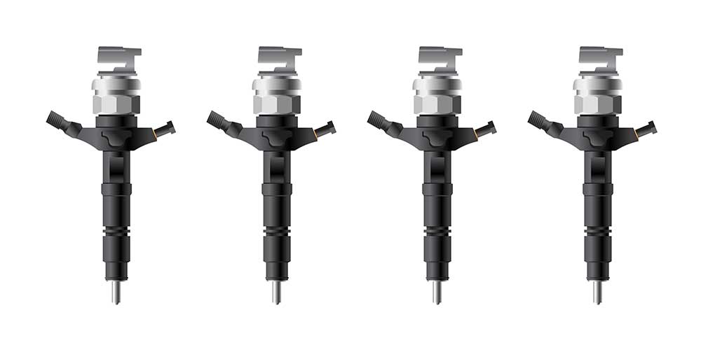
Electronic fuel injectors
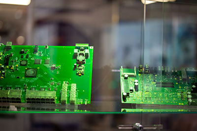
- Increase in Electronic Components: EFI was not the only electronic component introduced in vehicles in the 80s. Other parts came on board and needed a vehicle monitoring system to keep everything in check.
However, current vehicles with the second generation of this system collect data from multiple sensors in the vehicle and use it to regulate the car’s performance while alerting the driver of any problems.
This generation dictates the trouble codes and connectors used in cars, making it easier for mechanics to troubleshoot the error codes and rectify the problem more accurately.
Special Offer: Get $100 off your order!
Please email [email protected] for details.
How OBD Works
An OBD system consists of six components.
ECU
The ECU is the heart of the OBD system because it is the central connection point. It takes input from sensors to control parts, such as actuators, while sending data signals to the MIL and DTC.
Sensors
These components are the sources of data to the system. Sensors cover various vehicle parts, from the engine to the frame (chassis), and each of them sends a signal to the ECU that specifies its source and parameters.
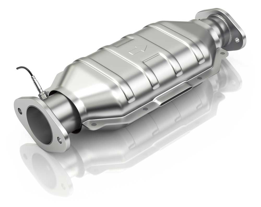
A catalytic converter with an oxygen sensor
Actuators
ECUs use sensor data to control actuators, such as fuel injectors, which regulate the engine’s performance to reduce emissions.
DTC
DTC is an acronym for Diagnostic Trouble Code. If the ECU receives sensor data that falls outside the acceptable range, it saves this information as a code known as DTC.
These fault codes are number and letter combinations that indicate the problem’s source. The first letter usually indicates the origin of the issue, and the five following digits indicate the specific problem details.
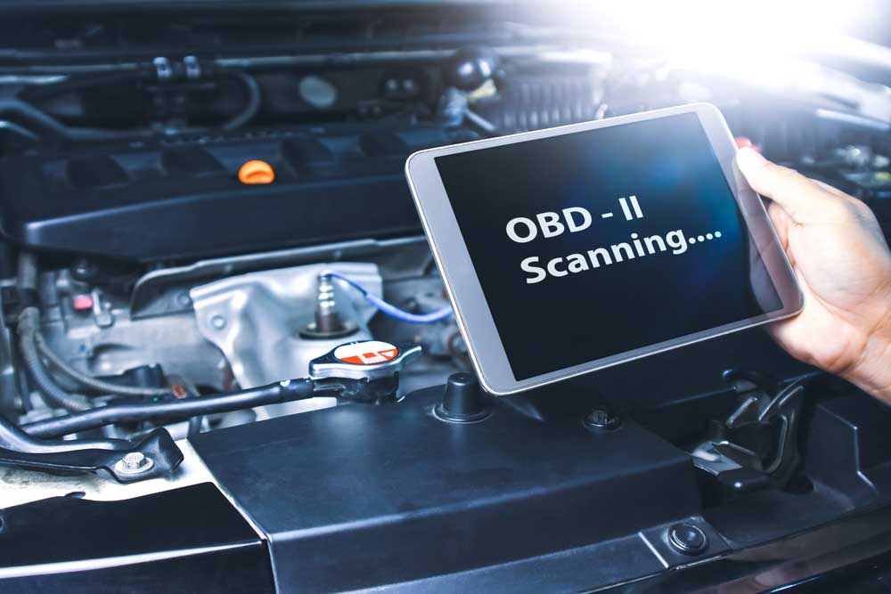
An OBD-II scanner scanning the system for DTCs
And it is vital to note that they can be manufacturer-specific or standardized. Here is the general OBD-II code starting format.
- Powertrain trouble codes begin with the letter P
- Manufacturer-specific powertrain error codes start with P1
- Chassis trouble codes begin with C
- Body error codes start with B
- Network trouble codes begin with U
MIL
After saving this DTC, the ECU sends the signal to your dashboard to turn on the appropriate light warning indicator. These lights are known as Malfunction Indicator Lights and are early warning systems.
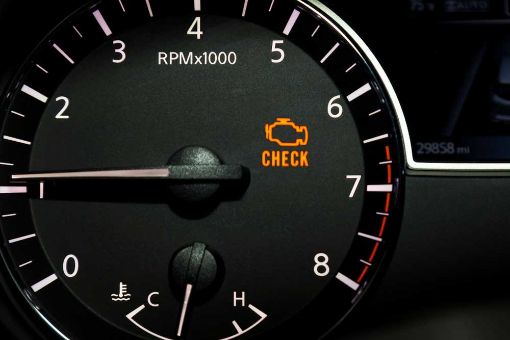
An illuminated check engine light on the dashboard
You should visit your service technician ASAP if the light stays on. But if it flashes (mostly the check engine light), go to your mechanic immediately.
DLC
The last component is the Diagnostic Link Connector, a port that provides access to read the DTCs via external test equipment (OBD scanner).
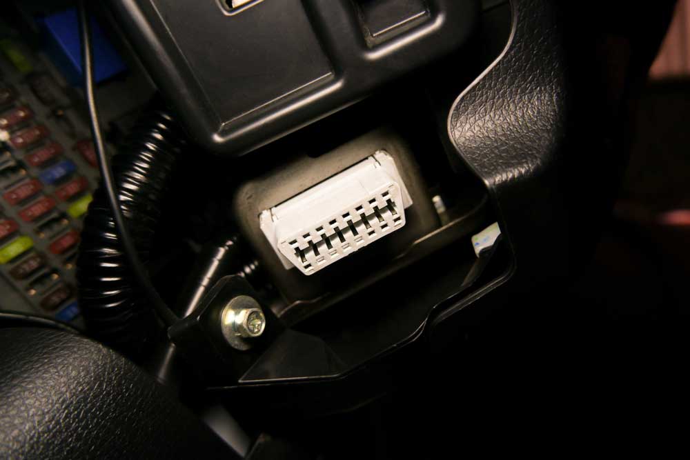
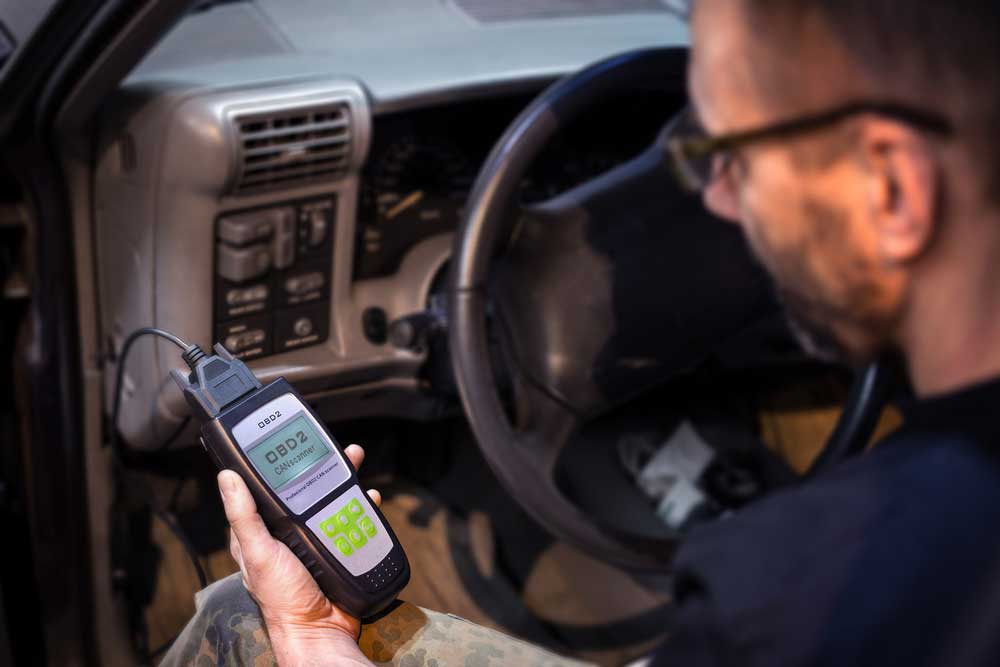
An OBD-II port under the dashboard
In most cars, this diagnostic interface is under the dashboard on the driver’s side, right next to your knee in your driving position.
OBD Generations
Although the OBD system came about in the 80s, it has only undergone one primary advancement: standardization.
OBD-I
The first generation of OBD was manufacturer-specific or proprietary technology.
Therefore, the error codes technicians could read from old vehicles with these systems varied broadly.
This design made it difficult for mechanics to troubleshoot the problem sources because each make or manufacturer had unique DTCs.
On top of that, these technicians had to purchase a tool and adapter cable for each make.
In most cases, only the dealerships could afford this car maintenance model of operation because they specialized in a few makes but with a large market.
OBD-II
The California Air Resources Board initiated the push to standardize OBD systems, albeit indirectly. It required all vehicles to have OBD capability in 1991 but didn’t issue any standards.
This requirement with zero guidance made it challenging for car manufacturers and vehicle owners to agree on which design to use, so CARB issued OBD-II in 1994.
OBD-II was a set of standards specifying the diagnostic system all vehicles sold in California should have.
Car manufacturers implemented this standard by 1996 car year models, which primarily defined the connector.
The SAE (Society of Automotive Engineers) and ISO (International Standardization Organization) came on board later. They issued the standards for digital information exchange between the ECU and the diagnostics tool when reading the DTCs.
After legislators passed the Clean Air Act in 2001, the EPA expanded the use of this OBD-II standard by requiring regular vehicle inspections to determine their emissions using this port.
In a nutshell, CARB standardized the hardware, which is a type 2 DLC connector.
This mechanism allowed mechanics to access the digital error codes saved by the ECU in any vehicle make and model using a single OBD scanner.
On the other hand, the SAE and ISO standardized the digital communication protocols, while the EPA introduced a standard for monitoring vehicle emissions to replace tailpipe testing.
CARB Standardized OBD-II Connector Pinout
This standard interface port has 16 pins with the following functions.
| Pin Number | Function |
| 1, 3, 8, 9, 11, 12, and 13 | Vendor-specific pins for manufacturer use. The SAE and ISO standardized communication protocols don’t require these pins. |
| 2 | The positive pin for SAE J1850 VPW and SAE J1850 PWM OBD-II protocols for variable pulse width modulated or PWM communication with GM and Ford vehicles. |
| 4 and 5 | Ground pins (connect to the vehicle’s chassis). |
| 6 | High pin for the double wire ISO 15765-4 CAN protocol communication at 1Mbps. |
| 7 | K-Line for the ISO 14230-4 and ISO 9141-2 protocols (provides asynchronous serial port communication). |
| 10 | Negative pin for SAE J1850 variable pulse width modulated or PWM communication with GM and Ford cars. |
| 14 | Low pin for the double wire ISO 15765-4 CAN protocol communication at 1Mbps. |
| 15 | L-Line for initializing the bus communication for ISO 14230-4 and ISO 9141-2 |
| 16 | Power line input from the car battery. |
The OBD-II port location is not standard, but as stated earlier, it is usually on the driver’s side under the dashboard.
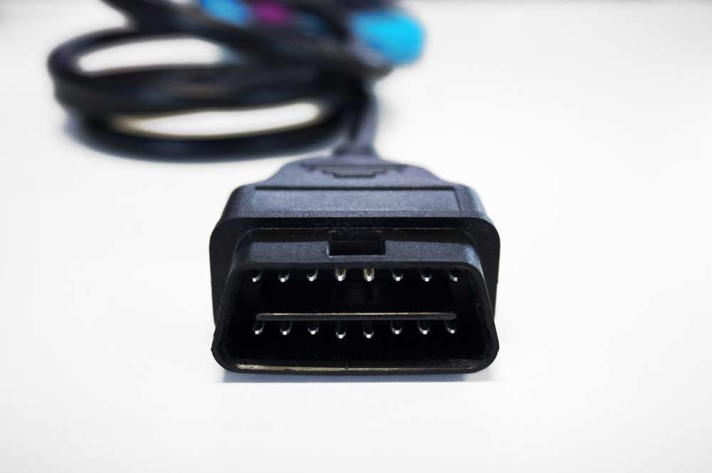
A 16-pin OBD-II plug connector for vehicle diagnosis
SAE and ISO OBD-II Digital Signal Protocols
These two bodies introduced these five communication signal protocols.
- SAE J1850 VPW: Variable Pulse Width Modulation communication for GM vehicles
- SAE J1850 PWM: Pulse Width Modulation communication for Ford vehicles
- ISO 14230-4 (KWP2000): Keyword protocol applied in most vehicle brands from the US, Japan, and Europe (Jeep, Subaru, Mazda, Land Rover, Nissan, etc.)
- ISO 9141-2: Communication protocol for all Chrysler car models, plus some European and Asian vehicles
- ISO 15765 CAN: Controller Area Network communication used in all vehicles built after 2008
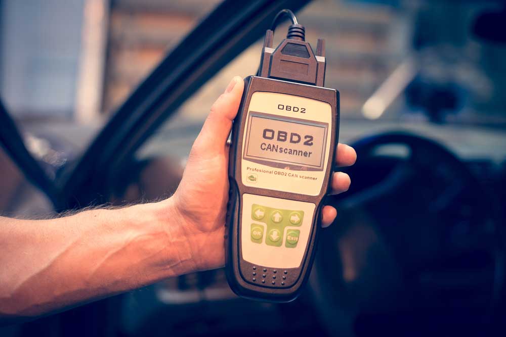
An OBD-II scanner that scans the CAN bus for vehicle diagnosis
Things To Consider When Shopping for an OBD-II Scanner
OBD-II system scan tools come in two types.
Display OBD-II Scanners
These vehicle diagnostic tools are the most basic because they are code readers that only read and show the fault codes.
So, you have to research these parameter IDs further to determine the source of the problem before getting into the repairs. The only advantage is their low cost.
A simple display OBD-II scanner
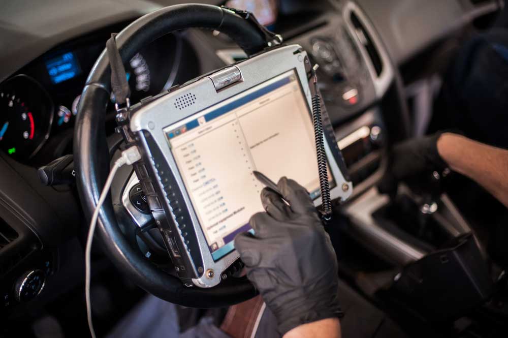
Diagnostic OBD-II Scanners
Diagnostic scanners are costlier than their display counterparts but give a more detailed vehicle issue analysis.
Some can access real-time data or stored DTCs to diagnose general or manufacturer-specific codes.
A diagnostic OBD-II scanner
The expensive ones can provide technical advice as TSBs (Technical Service Bulletins).
Conclusion
OBD is critical for modern vehicles because it helps narrow down the problem source from the complex electrical system. But it wasn’t as effective in its original state.
The pin and protocol standardization that occurred to form OBD-II-compliant vehicles made the system easier to use and cheaper for mechanics to handle a wide variety of models from different manufacturers.
That’s it for now, and we hope the article has been insightful.
Special Offer: Get $100 off your order!
Please email [email protected] for details.