In the IR detector circuit/sensor circuit, technologists often tackle their functions in detecting liquid level or proximity. Its operation involves using the reflection of an infrared beam to examine the distance present from the target. We will use an IR photodiode and an IR LED for the Infrared sensor circuit.
A major thumbs up on setting up this circuit is that there won’t be any physical contact with the liquid’s level that you are aiming to measure. Furthermore, you will only need one installation since it lacks corrosive elements, therefore, having high longevity.

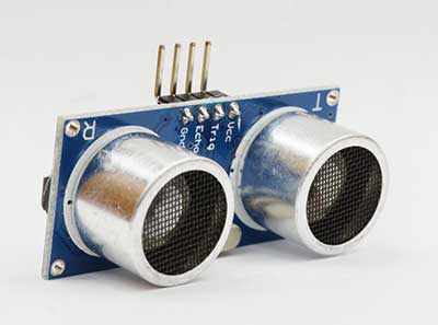
IR sensor
Contents
How does an IR detector work?
The principle of working with an IR detector applies three laws.
An infrared sensor works similarly to an object detection sensor. Its components, an IR photodiode, and the IR LED combine to form an octo-coupler/photocoupler.
- IR LED; operates by emitting Infrared radiation. Usually, the infrared receiver (in photodiode form) will detect the IR radiations via infrared transmitters. However, it’s impossible to see the radiation emitted by human eyes.
- IR Photodiodes; They stand out from standard photodiodes since their sole function is to detect IR radiation.
- After combining the above two components, the IR photodiode will be the receiver, while the IR LED will take the place of a transmitter.
- Note: If you use the IR receiver and transmitter’s combination, you should ensure that the receiver’s wavelength equals the transmitter.
- As an infrared LED generates infrared light, the infrared photodiode develops sensitivity and responds to the light.
- Ultimately, a proportion of the photodiode's internal resistance and output voltage change to the infrared light that the object has obtained.
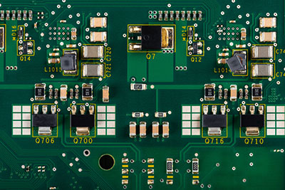
PCB with dual IR sensor.
In summary, the infrared transmitter produces an emission that proceeds to the object. On its arrival, some of the emissions reflect toward the infrared receiver. Based on the intensity of the IR receiver’s response, you can define the sensor output.
An illustration of how the IR sensor works
Special Offer: Get $100 off your order!
Please email [email protected] for details.
Type of IR Detector
You will encounter two types of IR sensors: the passive IR sensor and the active IR sensor.
Active IR Sensor
The active IR sensor has both a receiver and a transmitter. When using it, you will require a LED as the power source. The laser diode acts as an infrared imaging sensor, while the light-emitting diode is a non-imaging infrared sensor.
Their working principle revolves around energy radiation, whereby they receive and detect objects through radiation. Moreover, you can use a signal processor to get the essential information.
Examples of active IR sensor applications include break beam sensors and reflectance.
Passive IR Sensor
Contrary to an Active IR sensor, a Passive IR sensor only has detectors – no transmitter. Instead, the object will act as the IR source or transmitter. When the object releases energy, the infrared receivers will detect it. Then, the signal processor will analyze the signal and interpret it.
Further, the passive IR sensor has two other types - quantum IR sensor and thermal IR sensor.
Quantum IR sensors comprise a high detection time and response and largely depend on wavelength.
Thermal sensors have a slow response and low detection time.
Examples of its application include a bolometer, thermocouple-thermophile, and pyroelectric detector, among others.
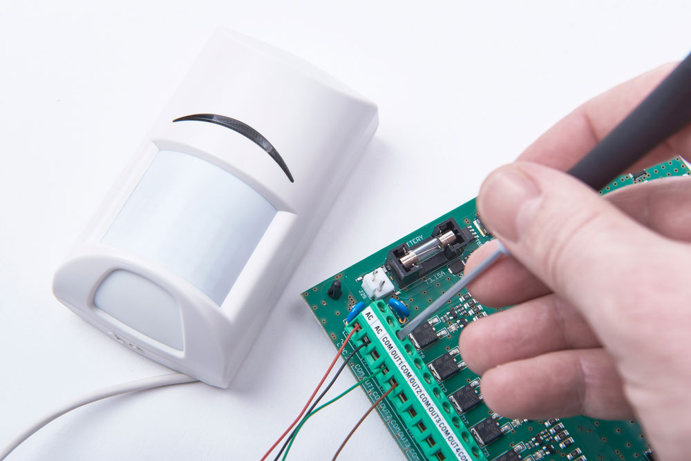
(alarm system)
How to build an IR Detector Circuit?
To construct
Note: avoid direct connection of the sensor diodes to light sources. At the same time, ensure the power supply has high-quality regulations.
Also, use the silver IR receivers with metal cases instead of the black plastic ones.
Parts list
The hardware components you will need for the infrared receiver circuit project include the following:
- Resistance R1 – 10K (4w)
- R2, R5, R6, R9 – 1K (4w)
- R3 – 33K(4w)
- R4, R8 – 1M (4w)
- R10 – 22K (4w)
- Diode D1 – IR LED
- D3, D4 – 1N4148 (75w/150 mA)
- D2 – IR photodiode
- D6, D7 – 1N 4002
- D5 – LED
- Trimmer Cermet R7 – 10K
- Capacitance C1, C4 – uF (63v)
- C3, C5, C6 – 100 uF (25v)
- C2 – 47pF (63v)
- IC2 – LM358
- IC3 – 7812
- Timer IC IC1 – NE555
- PNP transistor Q1 – BC558 (45V/800mA)
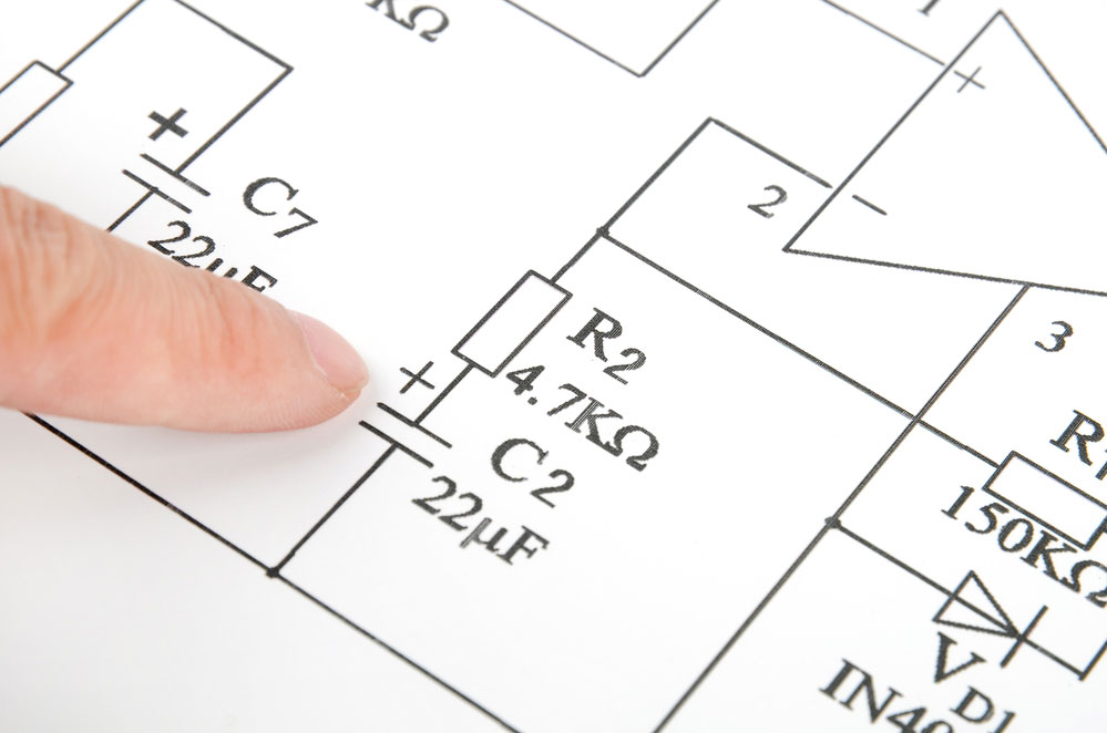
Circuit diagram
A comprehensive explanation of the circuit diagram involves;
- A transmitter section with an IR sensor that continuously transmits IR rays to the IR receiver module. The IR output terminal will vary depending on the amount of IR rays it receives.
- Then, the comparator circuit, an operational amplifier- LM339, receives the output for analysis purposes.
- If the IR receiver fails to receive a signal, the non-inverting input's potential will be lower than the inverting input's. Hence, the general outcome results in a lower comparator circuit and a non-glowing LED. On the other hand, if the IR receiver module receives some signal, the non-inverting input’s potential will be higher, plus low inverting input. Consequently, the comparator circuit shoots higher, and the LED begins to glow.
- R3, R2, and R1 guarantee that only a min. of 10 mA current can pass through the IR LED electronic devices.
- VR2 adjusts the output terminal.
- VR1 sets the circuit’s diagram sensitivity.
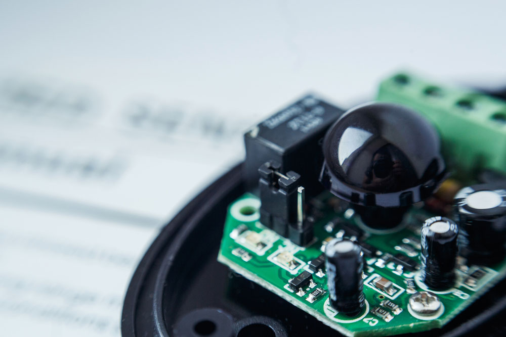
IR sensor with pin details.
Necessary steps
- First, start by connecting the required components using the circuit diagram.
- Then, connect the base terminal of the BC547 transistor to a single infrared LED.
- Next, connect it to the similar transistor’s base terminal using another infrared LED.
- Afterward, connect the 100Ω resistor near the residual pins in the infrared LEDs.
- Proceed by connecting the NPN transistor’s collector terminal to the PNP transistor’s base terminal.
- Referring to the circuit diagram, connect the 220Ω resistor and LED as indicated.
- Finally, finish by powering up the circuit to test if it is working.
How the circuit will work
After the infrared LED's detection, the light reflection from the object activates a minute current that supplies current all through the IR detector. Subsequently, the NPN and PNP transistors activate, enabling the LED to switch ON.
(Circuit schematic drawing)
Application of IR Detector Circuit
Here are several ways by which you can apply the IR detector circuit;
- First, In testing of phototransistors and IR remote controllers.
- Secondly, In detection circuits of IR beam
- third, In burglar alarm circuit
- In electrical power plants
- Infrared detector development has contributed to effective and augmented space explorations.
- An avalanche photodiode technology - a HgCdTe n/p photodiode, improves the low excess noise factor when applied in avalanche mode.
- A thermal IR detector measures IR radiation from objects like soil and water in IR imaging devices. It then records the object’s partial temperature in an image. Moreover, cooling an electronic detector to a low temperature ensures that the photons on the image are from the object itself and not from its ambient temperature. Ambient temperature can disrupt the response signal.
- In the medical field, the IR sensor is applicable in coronary CT angiography and helps optimize radiation dose during scanning more effectively than conventional detector technology. The IC detector performance also contributes to reduced image noise.
- It can help construct a gas sensor circuit with a non-dispersive infrared sensor. Gas analyzers with IR sensors use absorption characteristics of gas concentrations within the Infrared region.
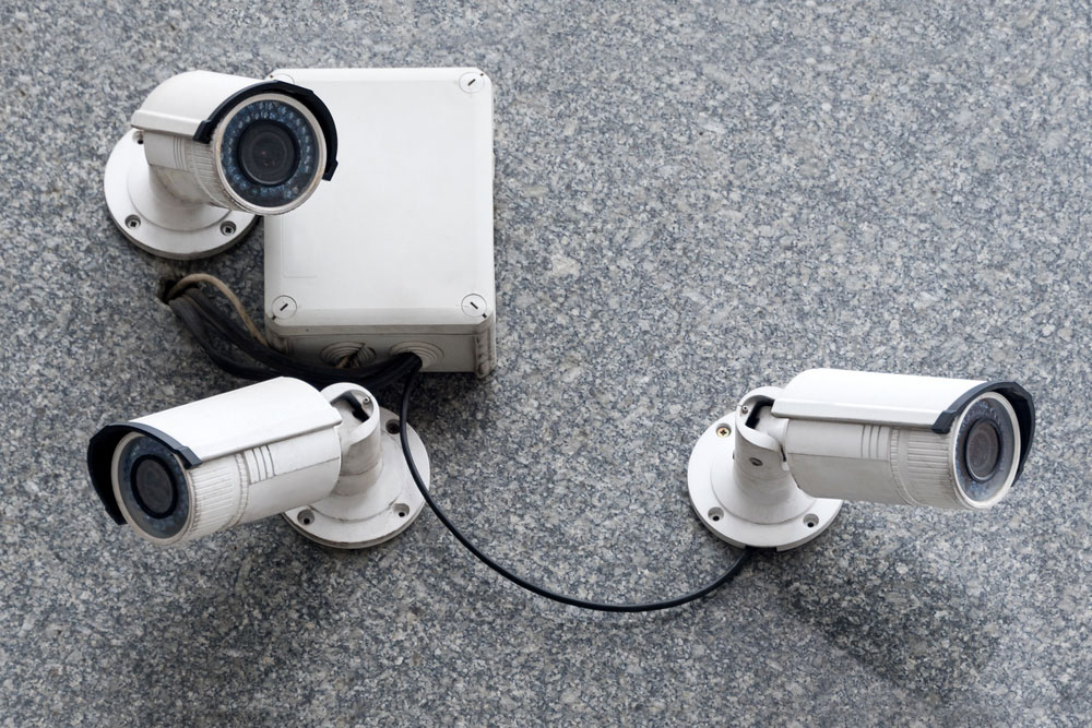
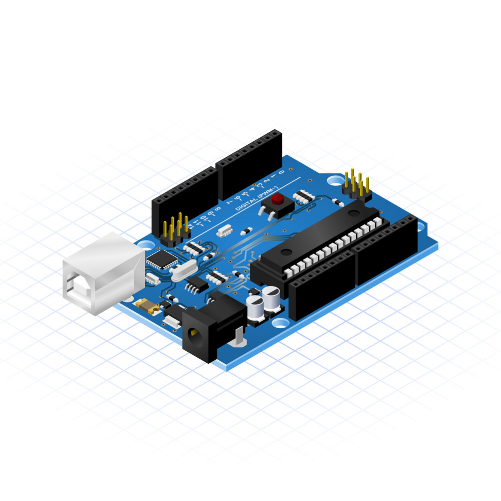
Infrared detector connected to an alarm mainboard.
Summary
To conclude, this electronic device, an IR sensor, has proven to be capable of achieving several technological tasks, such as measuring an object’s heat or detecting the object’s motion. It is often because the thermal radiation generated from objects in the infrared spectrum is invisible to the human eyes. Hence, the IR sensor solves the problem by doing the measurement.
There is still a lot more than we can discuss regarding the infrared sensor circuits. Therefore, we will be more than happy to help if you reach out to us.
Special Offer: Get $100 off your order!
Please email [email protected] for details.