Ever heard of the phrase, ‘Not all that glitters is gold’? Well, as a PCB buyer or distributor, there’s a higher chance of having the words come to life. Contrary to expectations, newly manufactured PCBs aren't always apt. That is to say, manufacturers can weld certain parts poorly with components having a massive fail. As such, it is essential to know how to new circuit board tester. Learning detection methods inclusive of instruments can save you a 'pocket-ache.' It enables you to realize faults beforehand. Therefore, if you need to know which tests you should do and instruments to use, keep reading through this article.
Contents
- 1. What Do We Need to Test on the PCB?
- 2. The Benefits of Circuit Board Tester
- 3. Circuit Board Testing and Circuit Board Tester Category
- 1. Visual inspection.
- 2. You need to check for short circuits and open circuits.
- 3. V/I test/ analog signature analysis.
- 4. Circuit Board Tester Method.
- In-Circuit test
- Flying probe test
- Automated Optical Inspection (AOI)
- Aging test
- X-ray inspection
- Circuit Board Tester--Function test
- 5.Circuit Board Tester-- Other Functional Tests
- 5.1 Types of other functional tests
- 5.2 Advantages of functional PCB testing
- 6. Circuit Board Tester-- Automated Test Equipment (ATE)
- System 8 modules include:
- ATE applications include:
- 7. Circuit Board Tester-- Commonly used In-Circuit testing for PCB testing
- 7.1 Equipment needed for In-Circuit testing
- 7.2 Advantages of in-circuit testing
- 7.3. Disadvantages of in-circuit testing
- 8. Circuit Board Tester-- Choose Tools and Test Methods According to the Actual Situation.
- Summary
Special Offer: Get $100 off your order!
Please email [email protected] for details.
1. What Do We Need to Test on the PCB?
PCB electrical components of different compositions have different functions. Such a malfunction can easily corrupt the other features, making the product prone to problems. So getting a quality product during the manufacturing process is, by all means, very crucial.
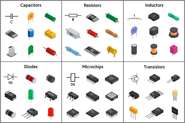
The items tested on PCBs include;
Resistors.
Resistors are small electronic devices producing a voltage by transmitting electrical currents. They are also an essential component of the PCB.
How to test a resistor:
- Isolating the resistors- prevents interference with other components that may distort the results.
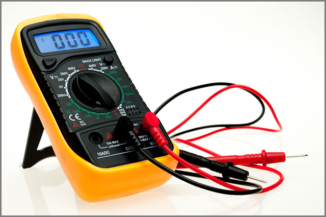
- Then, using a digital multimeter or analog meter, you connect the resistor to either of the two and run your test. It is, without a doubt, simple.
Results; a higher result indicates a faulty open resistor. Similarly, when you align other components together with the resistor, the work gets high, there might be a problem with the resistor.
Diodes.
Diodes transmit current in a single direction while blocking the wind in the opposite direction. Essentially, they have semi-conductive materials between terminals.
A method to complete the test:
- First, you need to disconnect one end of the diode from the PCB product.
- Afterward, use a multimeter or analog meter to locate the red and black meter probes.
- Lastly, connect the black probe to the cathode and the red probe to the anode. Then set the meter in ohms.
Result: if the diode leaks, two readings are recorded. Therefore, if there is a deviation, there will be resistance in the meter reading.
Capacitors
They are electrical devices storing energy as an electrostatic field. They have insulating materials placed between conductive plates.
Other than the above three that falls under electrical conductivity, you can also test;
- Mechanical strength; this includes the bending strength, peel strength, time delamination, and circuit board's density.
- We need to understand component placement, polarity, orientation, etc.
- Cleanliness; generally, cleanliness is the ability of PCBs to resist environmental factors like corrosion and humidity. With regards to that, it is essential to the PCB product's quality, reliability, longevity, and market readiness.
- Quality of hole wall; This ensures that it will not break the bore wall in application areas.
- Tests for the target environment; PCBs used in hot, humid, and cold climates are different. Therefore, complete the test to see which suits your needs.
- Lamination; a good lamination quality increases the lifespan of the product.
- Soldering quality. Understanding the solderability of the board with its components can lessen PCB fiascos and improve its quality.
2. The Benefits of Circuit Board Tester
The following benefits will enable you to comprehend why getting a tester for your PCB is vital;
- First, it will reduce the cost of repair. In that, you can fix any faultiness before starting to enjoy using your PCB.
- Furthermore, if you get to buy PCB products in bulk, you’ll be sure to reduce the number of returned products.
- Poorly assembled PCB components can pose lots of risks when being handled. Checking in advance can be lifesaving to you and your surroundings, but this can also ensure other production equipment safety.
- Reduces wastage in that; testers use small-scale assemblies and prototypes instead of complete products. After the test is full, you are at liberty to throw away the prototype without losing a full-scale crowd.
- Manufacturers are aware of the fact that they may lose their business alongside their customers. So, proper care and testing strategies are a priority to them. A benefit to the manufacturer is a happy customer equaling a thriving business.
3. Circuit Board Testing and Circuit Board Tester Category
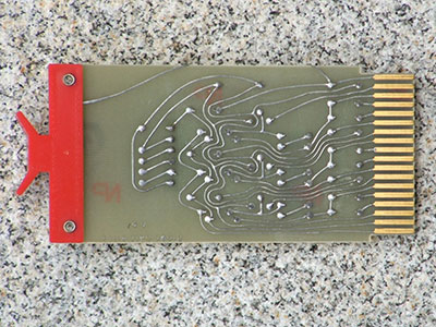
1. Visual inspection.
It is the simplest form of inspection as it involves visual check. It means a PCB buyer or distributor will only need to look at the product's board with bare eyes or uses magnification equipment/tester. In most cases, they will compare the functionality of the PCB against its documentation indicates.
Examples of visual inspection features can be;
- Thickness. Depending on the circuit board you’re using, it should be the desired thickness. Other than that, you can also inspect the surface roughness.
- Coating quality; see whether it’s firm and even or chipped. Besides, manufacturers need to put it in the right place.
- The product’s vias should be in the correct position, their measurements being as evident as spelled out by the document. Undoubtedly, poorly plated vias can create a short circuit between layers.
- Check for clarity of the conductive patterns together with the condition of the circuits.
Notably, this is the cheapest method of inspection, provided you don't settle for magnification equipment. It's also easy and takes the shortest time possible. On the downside, you can miss out on essential components such as hidden solder joints. The hidden solders are hardly visible. Likewise, you may not assess smaller parts.
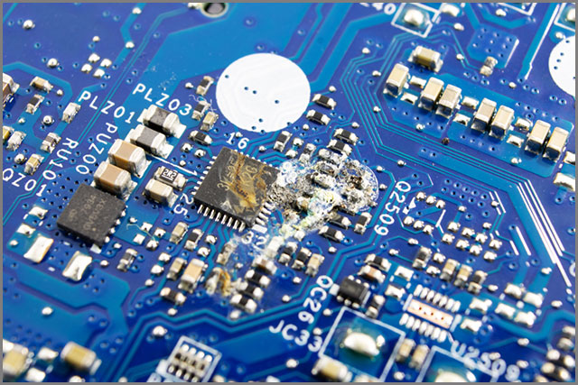
2. You need to check for short circuits and open circuits.
Short and open circuits can be frustrating to handle. It is especially true when they're interfering with the average current flow of the PCB. Early detection hence, prevents future disturbances.
You can quickly inspect circuits virtually. You’ll just need to have a good view of the entire surface of the PCB. As such, you can opt for a magnifying microscope to ease your work.
What to look-out for;
- If the temperature is very high, it will scorch the spots, causing the circuit board to burn out. The burn often appears brown.
- Poorly plated vias are a common cause of short circuits.
- Solder with cracks or blobs.
Another inspection method could be through infrared imaging. Some short and open circuits are internal. Therefore, they may not be noticeable as burn spots on the board's surface. It is where the infrared camera comes in. The camera helps you locate areas with high heat generation.
Testing the short and open circuit can be done by a Digital Multimeter. This equipment helps you check the resistance between different points in the rotation. Manufacturers equip useful multimeters with milliohms sensitivity and a buzz function to send some signals on faulty circuits.
3. V/I test/ analog signature analysis.
It is a non-powered, troubleshooting inspection technique for a detailed faultiness in the PCB.
You can use a VI (Voltage/ Current) tester to achieve this. Here, you’ll measure the network’s voltage and current response and display it as a Lissajous figure. On the waveform, you’ll see a vertical deflection for current and horizontal deflection for voltage.
The analog signature shows the overall state of the part under analysis. Later on, you make a comparison using an exemplary circuit board and a suspected faulty one.
Special Offer: Get $100 off your order!
Please email [email protected] for details.
4. Circuit Board Tester Method.
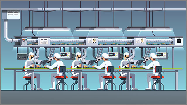
PCB buyers or distributors should be familiar with several test methods. The testing methods are just as significant to reputable electronic contract manufacturers (ECMs). Consequently, they off a variety of testing methods to their customers since they know of the costly consequences of a failed PCB.
Below are a few most reliable testers that are worth a trial:
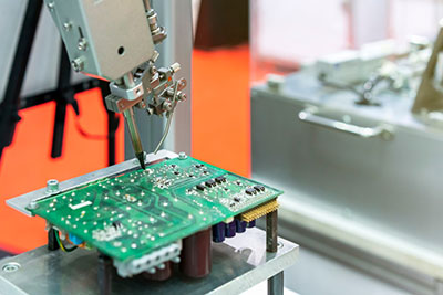
In-Circuit test
Also known as the Bed-of-nails test. It is used by ECMs and PCB operators to power up and stimulates the discrete circuitry on the board.
An in-circuit testing (ICT) is the most recommended type of PCB testers amongst other PCBs. It is costly, but the prices vary from one PCB board and fixture size to another.
ICT can check for short circuits, open circuits, resistors, capacitors, and other components. The user of the circuit board can know if the assembly is correct. You can do this procedure with a bed of nails type test fixture (Power-on tests) or a fixtureless (Power-off) test setup. ICT detects faulty components by assessing them independently, then making a replacement when the need arises. Falling under a fully automated test, it provides highly accurate information at high speed.
Some in-circuit testers can also test the functions of the in-built circuits. Usually, it isn't the norm. But, with proper assembly and board's design, it could work.
Flying probe test
Also known as the Fixtureless In-Circuit Test. This testing method is cheaper compared to an In-Circuit Test. The lesser cost could be because they lack fixtures- fixtures are the most expensive equipment used. Fixtureless testers have scarce limitations on board contact. They can virtually test boards with an available amount of nets. Also, they can allow test developers to complete programs faster.
It is non-powered. Meaning, it cannot power up aboard.
You can use it to check for;
- Diode issues
- Shorts
- Resistance
- Inductance
- Capacitance.
How it works;
First and foremost, the testing developers are to transform Computer-Aided Design (CAD) data provided by engineers into the relevant file.
Next, the new file will run and generate a new file with a matching format. Finally, we create all files to meet UUT (unit under test) test requirements and obligations.
After completion of the test program, the flying probe test follows suit. You then determine a testing item like shorts and opens. Select reference point data are conforming to UUT from CAD data. After you have fixed the UUT on the platform, you will conduct the programming to inspect the assembly issues.
FBT has certain advantages. Such as low cost, high conversion flexibility, and a short plus quick development cycle. I do not forget a rapid result during the prototype testing.
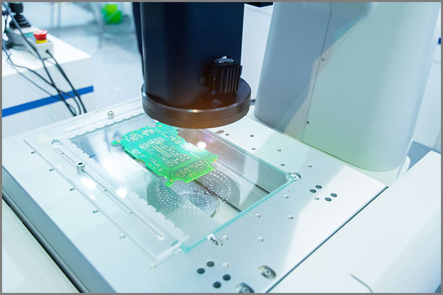
Automated Optical Inspection (AOI)
AOI is another crucial technique that ECMs apply in the manufacturing process and test of equipment with PCBs. It enables quick and precise inspection of PCB products, thus improving the board’s overall quality. It, however, doesn't power up the board. Let alone all parts not having 100% coverage.
AOI uses visual methods to check for defects in PCBs. They can detect defectiveness on surface features, for instance, nodules, scratches, and stains. In addition to that, AOI can see missing, incorrectly, and incorrectly placed components. The detection gives a clue on other affected components’ conditions, for example, thinning solders and open circuits.
It also uses a single 2D or two 3D cameras and takes photos of the PCB. AOI programs then make a comparison between your board and a much more detailed board scheme. Indifferences of your board to the schematics call for an immediate and thorough inspection.
Aging test
Manufacturers perform this test to determine the operational life of the PCB board. The most common type of aging test is Thermal Aging Testing (TAT). TAT tests the aptitude of components on the board to withstand extreme environmental conditions for an extended period.
TAT can stimulate a high temperature and complete analysis of the circuit board assembly chamber. Because the components are under extreme temperature conditions, this method accelerates the aging process.
Other than TAT, you'll also need to age standard PCB prototype samples before solderability testing. It is because solder layers deteriorate due to oxidation after being stored for long.
X-ray inspection
Advanced technological steps in creating PCBs have led to a sophisticated type of products sold in the market. Under such circumstances, you can't miss on products which are densely populated. Thus, seeing some hidden solder connections is impossible. So, in this case, we can use X-ray inspection equipment. It has advantages over other testing methods. Such as detailed inspection of solder points.
Components of a PCB absorb x-rays according to their atomic weight. In other words, heavier elements absorb more, with the lighter ones drinking less.
As an illustration, we can easily see soldiers with heavy elements such as tin during the X-ray inspection. On the other hand, components having lighter materials like copper are rarely visible.
Manufacturers do recommend this type of inspection when working with a densely packed product. Due to its complexity and newness, it can be expensive to acquire. Getting to use it rightfully can, therefore, put your money into fair use.
Circuit Board Tester--Function test
As the name depicts, a functional tester tests the functions of the circuit. The testing staff uses this test to confirm that your product will indeed work.
It's often done at the end of the manufacturing process to ensure that the manufactured parts won't fail soon or instantly after the test.
5.Circuit Board Tester-- Other Functional Tests
5.1 Types of other functional tests
- Solderability test: This test indicates whether the components attached to the board can withstand severe temperatures or not. Not to mention ensuring boards’ surface robustness and increases chances of forming unfailing solder joints.
- PCB contamination test: Flux residues and reaction products may contaminate your PCB. It often results in corrosion, degradation, and metallization. Complete the quiz to find the contaminated board and restore it to a functional state.
- Micro-section analysis/ Metallographic preparation: uses a 2D sample to help in identifying opens, shorts defective components, among others.
- Time-domain reflectometer (TDR): We can use impressive tracks for attenuating high-frequency TDR panels. They quickly spot unsoldered’ and shorts’ pins.
- Peel test: measures the degree of thermal strength required to peel the laminate from the PCB.
- Solder float test: determine the level of thermal stress a hole in PCBs can stand. Even honestly, they can point out possible delamination and bad solder joint connections.
5.2 Advantages of functional PCB testing
Merits of functional PCB testing include;
- In the end, it produces a defect-free PCB.
- We can perfectly pair these operations with other tests such as ICT and flying probes.
- It is excellent for detecting incorrect component values, functional and parametric failures.
- It ensures the product works as expected after the manufacture.
- May eliminate the need for expensive system tests as it covers up a lot of other tests.
6. Circuit Board Tester-- Automated Test Equipment (ATE)
The automated test system has replaced various test instruments, making PCB inspection faster and more accurate. They check for the digital functionality of in-circuits. Moreover, they provide a signature analysis of active and passive components.
ATMs can perform automated or computerized test procedures on a device under test. The test could include functional testing of ICs, analog, and digital components. Again, it can involve a single measurement made continuously at very high rates or multiple sizes made by a host of different instruments.
We can subdivide AT to become systems. For instance, there’s an ATE PCB repair system known as the ABI Electronic System 8. This system uses a selection of CD-drive-size modules to create a customized PC-driven PCB test station. They are faster and less costly in comparison to using traditional oscilloscopes and meters.
System 8 modules include:
- Board-level fault locator:
- Sixty-four test channels for multiple test methods for fault diagnosis testing of digital ICs (In-circuit/ out-of-circuit).
- IC connections status.
- V-I curve testing of components on unpowered boards.
- Analog IC Tester: for IC functional testing of analog ICs and discrete components (in the absence of programming or circuit diagrams). There’s a fully configurable V-I tester for the detection of defects on unpowered boards.
- Multifunctional instrument station: comprises of 8 high specification tests and measurement devices in a single module.
- Advanced test module has test combinations for flexible, comprehensive diagnosis, including thermal, connections, and analog signature analysis tests.
- Advanced matrix scanner: has 64 channels for fast data acquisition to test high-pin-count devices. It completes PCBs as well.
- Three output variable power supply Offers mandatory supply voltages to the unit under testing.
ATE applications include:
- power on/ power-off testing
- embedded real-time control
- calculation and logging
- automated test sequences
- digital and analog functional tests
- PCB testing and troubleshooting
- digital/ analog IC test
- visual short identification with audible/ visual indication of probe distance to short.
7. Circuit Board Tester-- Commonly used In-Circuit testing for PCB testing
7.1 Equipment needed for In-Circuit testing
- Software; the software is written in each board type that you should be testing, gives instructions. It has a guideline on what tests you should perform, between what points, and criteria for discerning the pass from the fail.
- Interface; The interface can place various circuit board fixtures on the tester.
- Securing means connected to the line and directly interact with the check plate. It has the appearance of a bed of nails (commonly known as sensor points); these are all specially designed for the board of directors. The sensor points connect to appropriate points on the board, then send back information to the tester.
- Analog scanner; scan and test the position and correct value of all analog components.
- Power supply simulation test; has the analog aspect for analog components such as regulators; and the digital part for testing digital features and scan devices.
- Analog-digital opens; It can process the output signal of the charge-coupled device.
7.2 Advantages of in-circuit testing
Due to the following advantages, we currently use ICT methods in most cases;
- It requires a minimal maintenance cost. It is because products tested by ICTs usually are of high quality with a minimal chance of failure.
- There’s almost a zero chance for operator error.
- It doesn’t take long to find errors. Therefore, this favors a large-scale buyer or distributor.
- You can easily interpret the results without much help.
- It favors medium to high volume through-hole conventional assemblies.
- It is easy to program when starting the testing process.
7.3. Disadvantages of in-circuit testing
The reason why buyers may opt for other testing methods is that ICT has downsides too. The drawbacks may not be in favor of everyone. So a couple of the disadvantages include;
- It is neither cost-effective nor time practical for smaller or prototype lots of production.
- The test fixture equipment is quite expensive.
- The test pins require constant cleaning and maintenance to prevent catastrophe.
- There can be inconsistent results should the pins fail to contact the appropriate test pads properly.
It could be flawed, but the truth of the matter is, the merits outweigh the limitations. It is still considered the best tester.
8. Circuit Board Tester-- Choose Tools and Test Methods According to the Actual Situation.
Now that you’re familiar with circuit board testers, it’s up to you to make the right choices. With regards to this article’s insight, different types of testers function according to specific PCBs. Therefore, check the requirements of any tester you might want to use.
Be sure to look out for;
- Affordability; can you easily purchase them?
- We need to test the durability of the product.
- Reliability; it’ll be better if a tester takes the shortest time in giving out error-free results.
- Environment; some of the testers to assess the severity of your domain.
You should carefully evaluate the condition you are in before a final decision. The mentioned above are a few examples and are not limited to your situation.
Summary
In conclusion, we sincerely hope that the information we've provided above will enable you to choose testers and go about the inspection. Some have been considered higher than others. However, since it takes two to tango, your own experience will verify this article.
In case of queries, clarifications, comments, name it, reach out to us. As always, we’ll be more than glad to share more knowledge and have a chat with you.
Special Offer: Get $100 off your order!
Please email [email protected] for details.