Contents
What is a VS1053 Chip?
The VS1053 chip is a highly versatile audio codec chip from VLSI, capable of decoding a wide range of audio formats, including MP3, AAC, WAV, MIDI, FLAC, WMA, and Ogg Vorbis. It belongs to VLSI’s slave audio processor family, designed to handle various audio processing tasks. This chip's key feature is its ability to load additional software into its RAM, enhancing its functionality beyond just decoding, making it adaptable for various applications.
In addition to its decoding capabilities, the VS1053 can perform recording tasks in three formats: 16-bit lossless PCM, IMA ADPCM, and Ogg Vorbis. PCM provides the highest audio quality, while Ogg Vorbis offers high compression with good quality, requiring a software plugin for real-time encoding. The chip's ability to handle both playback and recording tasks makes it suitable for various audio projects, from simple MP3 players to more complex audio processing applications.
On the decoding side, the chip can read eight file formats, which include the following.
- MP1 and MP2 (optional audio layers I and II for MPEG1 and MPEG2)
- MP3 (audio layer III for MPEG 1 & 2)
- Ogg Vorbis
- FLAC audio with software plugin (lossless format with up to 48kHz and 24 bits)
- MPEG4/2 AAC-LC(+PNS), level 3 HE-AAC v2 (SBR+PS)
- WAV (PCM+IMA ADPCM)
- General MIDI 1/SP-MIDI format 0
- All WMA profiles (4.0, 4.1, 7, 8, and 9) covering 5-384 kbps
For MP3 decoding, the chip combines CBR (Constant Bit Rate), VBR (Variable Bit Rate), and ABR (Average Bit Rate).
This chip comes in two variations.
- VS1053B-L: Houses all the encoding and decoding features above
- VS8053B-L: Lacks MP3, WMA, and HE-AAC decoders
Other Features
The VS1053 chip is more than an audio encoding and decoding chip because it has these extra features.
- Supports audio streaming
- Offers treble and bass controls
- Processes EarSpeaker spatial audio to simulate sound in a room with two loudspeakers
- Stereo headphone/earphone driver (30 ohm load maximum)
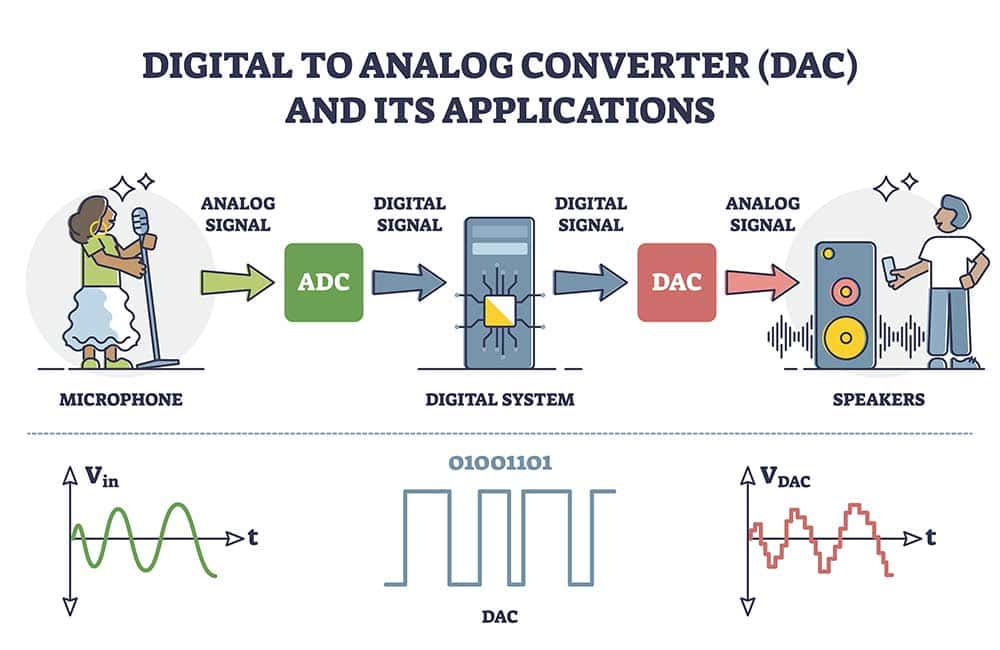
- Internal (on-chip) stereo digital-to-analog converter with zero phase error in between the channels
- I2S interface for linking to an external digital-to-analog converter
- UART interface for debugging
- Low power consumption with silent power on and off
- SPI flash boot for special applications
- Built-in PLL clock multiplier
- Runs using either a single 12-13 MHz or 24-26 MHz clock
- Smooth volume detection (zero cross-detection)
- Usable as a slave co-processor
- Separate voltages for the digital, analog, and GPIO pins
- Serial data and control interface
You can load software into the chip’s RAM using the eight VS1053 GPIO pins to increase these functions/features.
Special Offer: Get $100 off your order!
Please email [email protected] for details.
VS1053 Chip Detailed Breakdown
Physical Dimensions
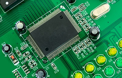
The VS1053 comes as an LQFP-48 package that measures 7x7x1.4mm. LQFP is an acronym for Low-profile Quad-Flat Package, meaning the chip is thin (1.4mm) and is a surface-mount type with component leads or pins extending from the four sides.
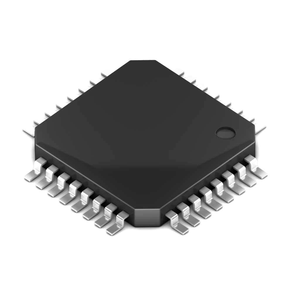
A Quad-Flat Package with 32 pins
The number 48 implies the component leads are 48 or 12 on each side.
The package is Lead-free and RoHS-compliant (the electronic equipment does not have certain hazardous substances).
Pin Functions
Each pin has a specific function summarized in the table below.
AI (Analog Input Pins)
| Pin No. | Pad Name | Function |
| 1 | MICP/ LINE1 | Line-1 in/self-biasing +ve differential mic input |
| 2 | MICN | Self-biasing -ve differential mic input |
| 18 | XTALI | Crystal input |
| 48 | LINE2 | Right channel line-2 in |
DI (Digital Input Pins/CMOS Input Pads)
| Pin No. | Pad Name | Function |
| 3 | XRESET | Schmitt-trigger input/ active low asynchronous reset |
| 13 | XDCS/ BSYNC | Byte sync/ data chip select |
| 23 | XCS | Chip select input (active when low) |
| 26 | RX | UART receive (link to IOVDD if unused) |
| 28 | SCLK | Serial bus clock |
| 29 | SI | Serial input |
| 32 | XTEST | Reserved to testing functions (link to IOVDD) |
DGND (Core or I/O Ground Pins)
| Pin No. | Pad Name | Function |
| 4 | DGND0 | I/O & core ground |
| 16 | DGND1 | I/O & core ground |
| 20 | DGND2 | I/O & core ground |
| 21 | DGND3 | I/O & core ground |
| 22 | DGND4 | I/O & core ground |
| 35 | GND | I/O ground |
CPWR (Core Power Supply Pins)
| Pin No. | Pad Name | Function |
| 5 | CVDD0 | Core power supply |
| 7 | CVDD1 | Core power supply |
| 24 | CVDD2 | Core power supply |
| 31 | CVDD3 | Core power supply |
IOPWR (I/O Power Supply Pins)
| Pin No. | Pad Name | Function |
| 6 | IOVDD0 | I/O power supply |
| 14 | IOVDD1 | I/O power supply |
| 19 | IOVDD2 | I/O power supply |
DO (Digital Output Pins/CMOS Input Pads)
| Pin No. | Pad Name | Function |
| 8 | DREQ | Data request input bus |
| 15 | VCO | Clock VCO output (for testing purposes only) |
| 27 | TX | UART transmit |
DIO (Digital Input/Output Pins)
| Pin No. | Pad Name | Function |
| 9 | GPIO2/ DCLK | General purpose IO 2/ serial input data bus clock |
| 10 | GPIO3/ SDATA | General purpose IO 3/ serial data input |
| 11 | GPIO6/ I2S-SCLK | General purpose IO 6/ serial clock bus interface |
| 12 | GPIO7/ I2S-SDATA | General purpose IO 7/ serial data input bus interface |
| 25 | GPIO5/ I2S-MCLK | General purpose IO 5/ master clock bus interface |
| 33 | GPIO0 | SPI boot (General purpose IO 0). Use it with a 100kΩ pull-down resistor. |
| 34 | GPIO1 | General purpose IO 1 |
| 36 | GPIO4/ I2S_LROUT | General purpose IO 4/ LROUT bus interface |
AO (Analog Output Pins)
| Pin No. | Pad Name | Function |
| 17 | XTALO | Crystal output |
| 39 | RIGHT | Right channel output |
| 42 | GBUF | Headphone/earphone common buffer (do not ground) |
| 46 | LEFT | Left channel output |
DO3 (Digital Output Pin/CMOS Tri-Stated Output Pad)
| Pin No. | Pad Name | Function |
| 30 | SO | Serial output |
APWR (Analog Power Supply Pins)
| Pin No. | Pad Name | Function |
| 37 | AGND0 | Analog ground low noise reference |
| 38 | AVDDO | Analog power supply |
| 40 | AGND1 | Analog ground |
| 41 | AGND2 | Analog ground |
| 43 | AVDD1 | Analog power supply |
| 45 | AVDD2 | Analog power supply |
| 47 | AGND3 | Analog ground |
AIO (Analog Input/Output Pin)
| Pin No. | Pad Name | Function |
| 44 | RCAP | Filtering capacitance for reference |
What Is a VS1053 MP3 Shield?
This shield expands the capabilities of the VS1053 chip and enables you to mount it on a microcontroller board, such as Arduino.
The component introduces the following features.

An MP3 shield
- A microphone for recording
- Stereo and headphone outputs
- Power indicator
- 2.8V and 3.3V LDO AMS-117 chips for supplying up to 800mA
- 12.288 MHz crystal
- SD card slot
- Single 5V DC power supply
Wrap Up
The VS1053 is a must-have chip for microcontroller audio projects because it has the required versatility, including multiple encoding and decoding formats.
You can simplify its usage using the VS1053 MP3 shield, which plugs it into microcontroller boards. So you don’t have to solder the chip to a pad.
You can read more about Arduino shields here, and contact us if you have any questions.
Special Offer: Get $100 off your order!
Please email [email protected] for details.