About voltmeter is, There are instances when you want to know the voltage, or the potential electrical difference, between any two points within a circuit. For example, maybe you're trying to understand the operation of your car's battery. Eventually, you'd need to connect a PCB-produced voltmeter across your battery's positive and negative terminals.
If your automobile battery is fully charged, you'll notice a voltmeter will read 12.6 volts. In other words, the voltmeter shows you that the potential difference between your battery's two terminals is 12.6 volts. A voltmeter is a very useful tool for professionals and DIYers alike.
This article will discuss a straightforward digital panel-type voltmeter that displays voltage using a single IC L7107 and other basic components. Read on to learn more.
Contents
What Is Voltmeter IC?
A voltmeter IC, or integrated circuit, assembles electronic components on which thousands or millions of miniaturized transistors, resistors, and capacitors are fabricated. The ICL7107 from Intersil is a very popular and accurate IC for voltage measurement. It's a versatile 3.5-digit analog-to-digital converter (ADC) that consumes less than 200 mA current.
A single ICL7107 has built-in circuitry for seven segment decoders, display drivers, a clock, and a reference voltage source. The simple, high-performance IC can show 0-2000 volts with an accuracy of 0.1%. You can use the circuit to give an alphanumeric display in digital panel meters.
Special Offer: Get $100 off your order!
Please email [email protected] for details.
How Does a Digital Voltmeter Work?
A digital voltmeter (DVM) measures the value of AC or DC voltage and displays it directly in numeric form. Unlike an analog voltmeter that displays results by pointer deflection on a continuous scale. Factors like input impedance, temperature, and power voltage variations can affect the measurement accuracy of a DVM.
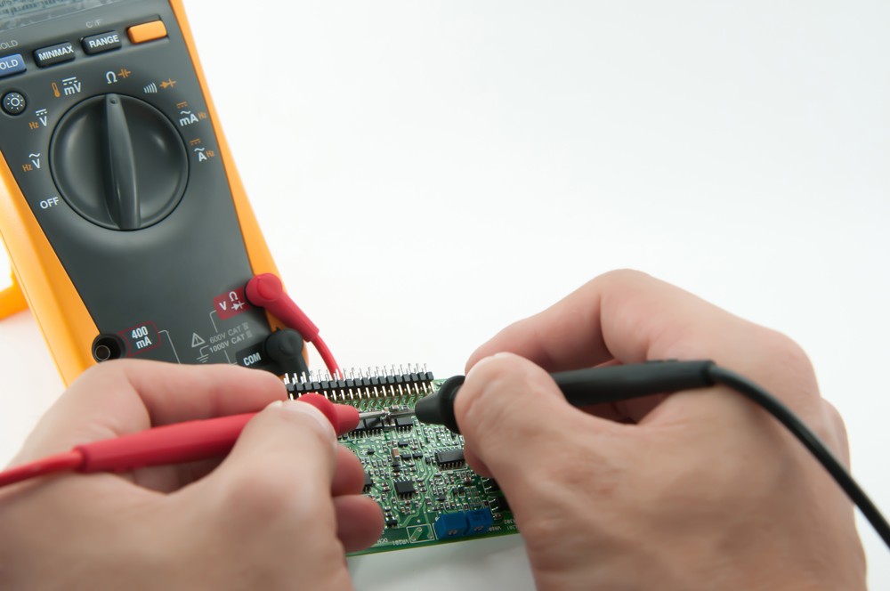
Fig 1: Hands-Checking Socket Voltage Using Digital Voltmeter
A DVM's input range may vary from ±1 V to 1000 V. In case the voltage range is less than 20 V; a precision DVM will provide input resistance of 1 GΩ or higher. Here's a figure showing the block diagram of a simple digital voltmeter:
From this diagram, you can see that an analog-to-digital converter follows the attenuator. The ADC differentiates between various types of digital voltmeters (more on this later).
Furthermore, the circuitry consists of a counter section, where we often use a decade counter. Then there's the read-out system for displaying the input signal's digital voltage.
Now, let's get into the actual working principle of a digital voltmeter. The figure below will help you get a deeper understanding of the working of a DVM.
A series of resistance inside the attenuator reduces the input signal. Therefore, the voltage at point A will be similar to the input voltage Vin.
If you apply the voltage division rule, it becomes clear that point B will have a lower voltage than A. Likewise, point C will have a lower voltage than both A and B, and so on. That's how the attenuator works.
Ideally, the role of the attenuator is to minimize the excess voltage that could otherwise damage other components of the device. We're using decade attenuation to get the decimal count in a digital voltmeter. That means performing attenuation will result in powers of 10.
So, our input voltage at the input of ADC will be Vin/N.
: N = 1, 10, 100, 1000
To get the digital output, the ADC in the circuit helps convert analog signals to digital ones. A digital signal contains 2 levels, such as 0 and 1.
Once the input at ADC Vin/N changes to digital format, we get a train of digital pulses. The width of a pulse is proportionate to the input signal at the ADC.
These digital pulses enter the counter unit to be counted. A single-decade counter contains 3-decade counters that are cascaded as a whole. These counters can count from 0-9, which is 10 counts. That means 3 counters will count up to 1000.
DC 7447 produces a 7-segment display from the BCD value. As a result, the system will display the input value in digital format. The decimal point selector is at the very end of the circuit. This will choose the decimal's position based on the voltage's magnitude.
Special Offer: Get $100 off your order!
Please email [email protected] for details.
What Are the Types of Digital Voltmeter?
Digital voltmeters are classified based on ADC conversion methods, such as:
-
Ramp Type DVM
A ramp-type DVM consists of a ramp generator, a time measurement unit, and a voltage-to-time conversion unit. Its operation is based on the measurement of the time it takes for a linear ramp voltage to rise from 0 to the input voltage level and vice versa. The input to be measured is provided at input voltage.
You'll need to feed this input to the attenuator circuit to amplify or attenuate the signal accordingly. A ramp-type DVM uses an electronic time-interval counter to measure the time interval. A digital display will show the results as several digits. You can easily design this circuit at a low cost.
-
Dual Slope Integrating Type DVM
The dual-slope integrating type DVM has five basic blocks: an Op-Amp integrator, a level comparator, a clock, decimal counters, and logic circuitry. You apply the analog input to the integrator through switch S for a given period. During that period, the comparator will raise the input voltage level to the desired positive value.
The switch shifts to reference voltage at the end of a known period. On the other hand, the output of the integrator drops until it's lower than the comparator reference voltage. The system notifies the time control logic to stop the count this time. The count displayed at the digital read-out will be proportional to the input voltage and the measured value.
-
Integrating Type DVM
The integrating type DVM uses the voltage-to-frequency conversion technique. This technique generates a train of pulses, and the input voltage magnitude is proportional to the pulse generation rate. In other words, the rate at which these pulses are formed depends on the measured voltage.
These pulses occur in a definite time interval. Because the frequency of pulses is proportional to the input voltage, these pulses are counted. The number of pulses is considered the input voltage.
-
Successive Approximation DVM
As the name suggests, this digital voltmeter uses a successive approximation converter. It can display 1000 readings per second. It would be best to input a start pulse at the start/stop Multivibrator. You also set the control register's MSB high and leave other bits low. That means an 8-bit control register would show 10000000 readings.
In that case, the DAC output will be half the reference voltage. Now, the comparator compares the converter's output and input voltage. Moreover, it delivers an output that will result in the control register retaining 1 in its MSB.
The circuit has a ring converter that advances one count next. When a 1 is shifted in the second, the control register's MSB will change to 11000000.
Therefore, the DAC reference increases by one increment, and the subsequent input voltage appears. That way, the measurement cycle continues through successive approximation.
The measurement cycle stops when it gets to the last count. At that point, the control register displays the final approximation of the input voltage in digital format.
How to Make a Digital Voltmeter Using ICL7107
Thanks to the ICL7107 A/D voltage processor chip from Intersil, we can easily design an accurate digital voltage measurement meter. The ADC used here is of the dual-slope type ADC.
Required Components
- IC7107
- LM7805
- LM555
- Regular anode 7-segment LED display (4)
- PCB
- Terminal Block 2 Pin (2)
- 47K
- 22K
- 10K
- 1K (5)
- 120K
- Pot 5K
- 10uF (2)
- 100nF (3)
- 220nF
- 100pF
- 47nF
- 1N4148 diode (2)
- Berg Sticks (2)
- Power Supply 9v/12v
- 8-pin IC base
- 40-pin IC base
- Probe or wire
Circuit Diagram
As you can imagine, the unit is a fully-fledged digital voltmeter whose ADC reads direct voltages from 0-199 volts. However, it's possible to shorten or widen the range as necessary.
To do that, alter the value of the 1M resistors aligned with the series input terminal. Whereas a 1M resistors provide a full scale of 199.99V, 100K would change that to 19.99V full scale.
The circuit operates on a dual +/-5V supply. You can acquire the +5V from a standard 7805 IC regulator circuit. The ICL7660 automatically creates the -5V to be fed to pin#26 of the L7106 IC.
Steps
Step 1: PCB Layout
You must assemble the circuit on the best-quality printed circuit board in the first step. And this is to ensure all electronic components are affixed in designated positions on the outer layers before soldering.
Step 2: Assemble Components and Test the Circuit
Step 2 components are electrically connected and attached to a printed circuit board. There are two methods to use: through-hole and surface mount. No matter the method, be sure to bring together everything so that the circuit does its intended purpose.
Step 3: Calibrate the Circuit
For calibration, turn on the circuit and short the input terminals. Then carefully adjust the R6 until the display reads 0V.
Step 4: Solder the Components on the PCB
solder the components together to affix them to the PCB when all is said and done. You'll need a quality soldering iron to produce the right amount of soldering temperature.
https://www.youtube.com/watch?v=tEy0S2XL0Mg
Conclusion
You learned everything you needed to know about voltmeter IC in this post. Hope you found this post informative. If you like it, share it with your friends so they can learn too.
Special Offer: Get $100 off your order!
Please email [email protected] for details.