If you work with microcontrollers and embedded systems, it is essential to understand the available communication protocols. The typical ones are SPI, UART, and I2C. All three provide serial data communication but have several differences. We will do an SPI vs. UART comparison in this article to highlight the unique features of each protocol and help you pick the most suitable one for your project. Let's get started!
Contents
- What is SPI?
- SPI Working Principle
- SPI Benefits and Drawbacks
- What is UART?
- UART Working Principle
- UART Benefits and Drawbacks
- Differences Between UART and SPI
- Hardware vs. Protocol
- Interface Diagram
- Number of Devices
- Speed
- Type of Communication
- Number of Wires/Pins and Pin Designations
- Error Checking
- Protocol
- Software Addressing
- SPI vs. UART: Distance
- SPI vs. UART: Size
- SPI vs. UART: Cost
- SPI vs. UART: Which Should I Choose?
- Wrap Up
Special Offer: Get $100 off your order!
Please email [email protected] for details.
What is SPI?
Serial Peripheral Interface is a serial communication protocol for full-duplex communication that uses the following four wires.
- MISO (Master Input, Slave Output)
- MOSI (Master Output, Slave Input)
- SCLK (Serial Clock Line)
- SS/CS (Slave Select/Chip Select)
SPI protocol enables communication across nearly all devices with clocked serial streams.
SPI communication uses a master-slave communication method that enables high-speed data exchanges. It must use four wires to be able to handle multiple slave devices using one master. Also, SPI communication is synchronous and uses the master’s clock signal to keep the master and slave devices operating on similar frequencies.
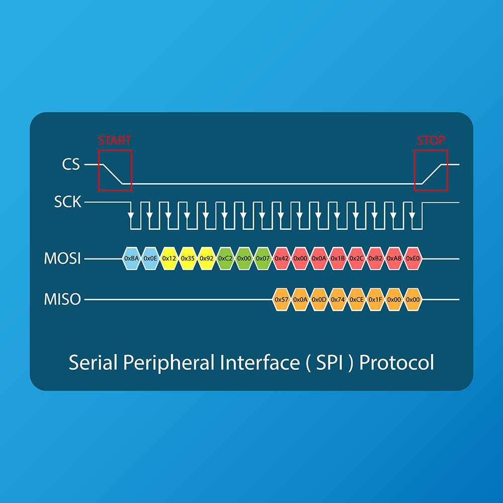
The SPI protocol clock interface
SPI interfaces are typical in microcontroller connections, display modules, and SD cards due to their full-duplex fast data transmission rate.
The SPI protocol continues to evolve, with SPI speed being the most significant evolution. It can achieve speeds higher than 100MHz and send the data in several formats, such as single, dual, and quad I/O SPI. The more the I/O, the faster the data transfer rate.
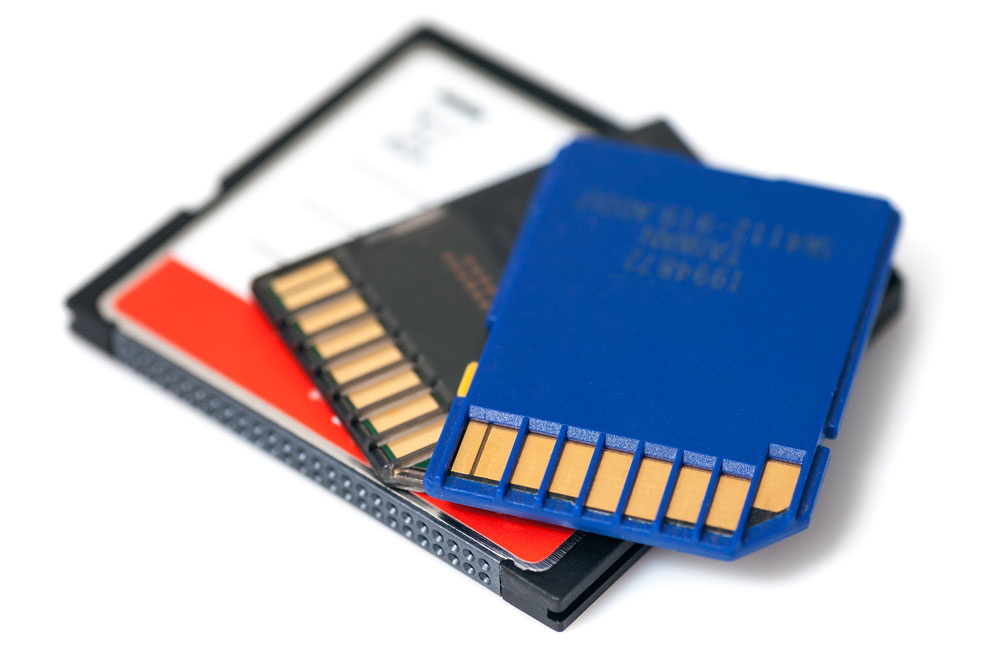
An SD and compact flash memory card
SPI Working Principle
The synchronous protocol operates in two ways. It can select each device with a Chip Select (CS) line (every device should have a separate CS line). Daisy chaining is the second option. With this option, each device connects to the other's data in line with its data out. There is no limit to the number of slave devices you can connect in the daisy chain.
Since the serial protocol involves master-slave communication, the control device (master) initiates data transmission to the slave). Additionally, it uses separate data signal lines to increase the transmission speed between the CPU and peripheral devices, especially when dealing with numerous slaves.
You will need tools like oscilloscopes and logic analyzers to design and develop the SPI bus.
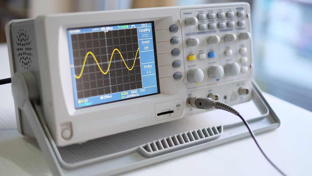
A digital oscilloscope
SPI Benefits and Drawbacks
Benefits
- Provides full duplex communication
- Fast data transmission speed
- Easy software implementation
- No need for start and stop bits
- Uses a shared clock signal from the master (no need for slave precision oscillators)
- Simple slave addressing system
Drawbacks
- Requires complex wiring if dealing with two or more slaves
- No data received acknowledgment or error checking
- Uses four wires
- It can only accommodate one master
Special Offer: Get $100 off your order!
Please email [email protected] for details.
What is UART?
UART refers to Universal Asynchronous Receiver Transmitter. From a high level, UART is as simple as a microchip for facilitating communication between a computer and the serial devices attached to it.
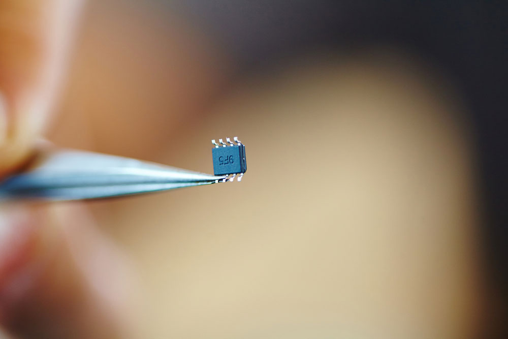
A microchip
Like SPI, UART supports full duplex serial communication but asynchronously. It requires a single wire to transmit data and another for receiving data. So it is slower than the 4-wire SPI. The peripheral hardware converts the incoming and outgoing data into a serial binary stream that goes through the two-wire interface.
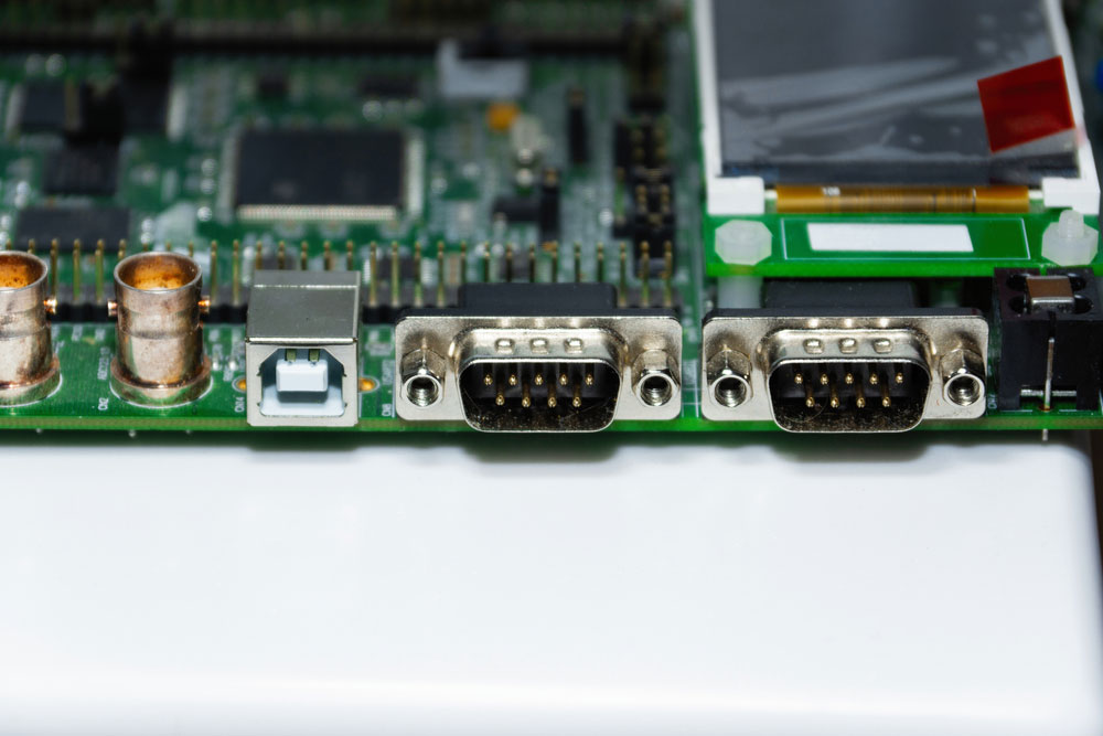
RS-232 and USB type B UART interfaces on an Evo dev board
Additionally, UART can only handle a single transmitter and receiver, and since it is asynchronous, the simple protocol does not need clock synchronization.
Instead, a UART data transmission uses packets. The packet consists of a data frame, a parity bit for error detection, and a start bit plus one or two stop bits for serial data transfer.
Both the transmitter and receiver in UART feature control logic, shift registers and hold registers.
A shift register
UART Working Principle
UART asynchronous communication can function in the following three ways.
- Simplex: Data transmission occurs one-way
- Half-Duplex: Data transmission occurs either way
- Full-Duplex: Data transmission occurs both ways simultaneously
Data flows from the transmitting UART's TX to the receiving UART's RX (TX is transit data while RX is receiving data). The transmitting UART gets its data from another component's data bus, then includes start, stop, and parity bits to create the data packet. Besides these three, the transmitter and receiver must also agree on the baud rate and data length configuration.
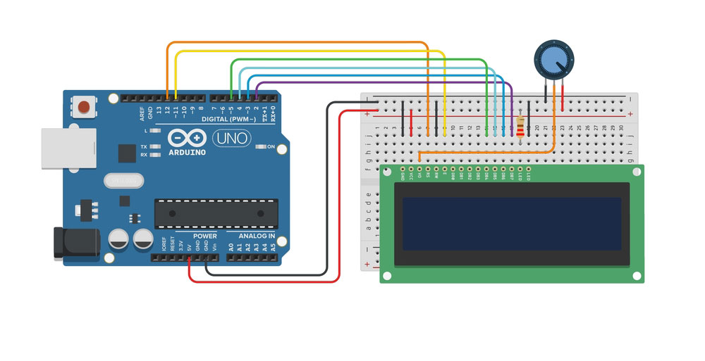
An Arduino UNO microcontroller. Note the Tx and Rx pins
On receiving the packet, the RX identifies the start bit, then reads the baud rate bits (usually 115,200) to check the data transmission speed. The transmitting and receiving UARTs should run at approximately the same baud rate. If the rate's difference exceeds 10%, the bit timing can go off. And if the timing goes off, the data will become useless.
UART Benefits and Drawbacks
Benefits
- It does not need clock synchronization
- Easy to implement
- Requires only two wires
- Parity bit for error checking
Drawbacks
- 9-bit limited data frame size
- Transmits data at slower speeds
- Can only use a single master device & slave device
Differences Between UART and SPI
Although both SPI and UART are serial communications protocols, they have significant differences in the following areas.
Hardware vs. Protocol
You can consider UART hardware (a microchip) from a high level, while SPI is a communication protocol.
Interface Diagram
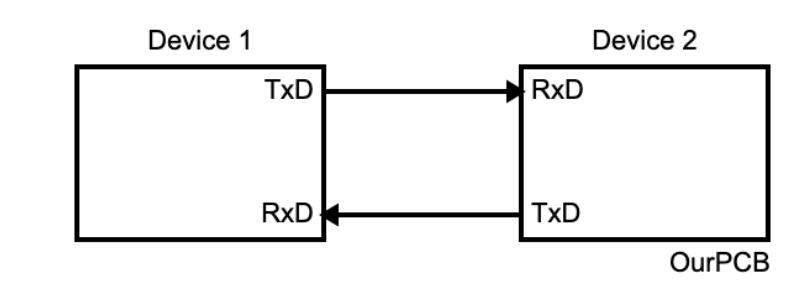
A connection between two devices using the UART protocol
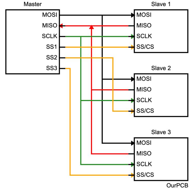
Connections between a master and three slaves using the SPI protocol
Number of Devices
UART can only handle two devices for one-to-one communication. However, the master device in SPI communication can accommodate multiple slave devices. But the master should have a separate SS/CS line for each slave.
Speed
SPI has a faster data transmission rate than UART in some cases. UART supports a maximum data rate of 230 to 460Kbps, while SPI can support about 10-20Mbps.
Type of Communication
UART is asynchronous, while SPI is synchronous. Therefore, SPI requires clock synchronization from the master device.
Number of Wires/Pins and Pin Designations
UART uses two pins, while SPI requires at least four. UART pins are TxD for Transmit Data and RxD for Receive Data. On the other hand, the pins designated for SPI include the following.
- MOSI: Master Output, Slave Input
- MISO: Master Input, Slave Output
- SCLK: Serial Clock
- SS/CS: Slave Select/Chip Select
Error Checking
SPI does not do error checking. However, UART wraps the data frame using start, stop, and parity bits. Parity bits are for error detection.
Protocol
UART uses one start bit and one stop bit for every eight data bits. But with SPI, each manufacturer can have specific protocols to communicate with the peripheral modules. Therefore, you need to read the datasheet to understand the read/write protocol to establish SPI interface communication.
Software Addressing
Since UART creates a one-to-one direct link between devices, there’s no need for software addressing. However, SPI must have slave select lines to communicate with any slave connected to the master module.
SPI vs. UART: Distance
UART can send data over shorter distances (50 feet or less) than SPI. But you can convert the low voltage 5V UART to higher voltages (+12V for logic 0 and -12V for logic 1) for long-distance communication.
SPI vs. UART: Size
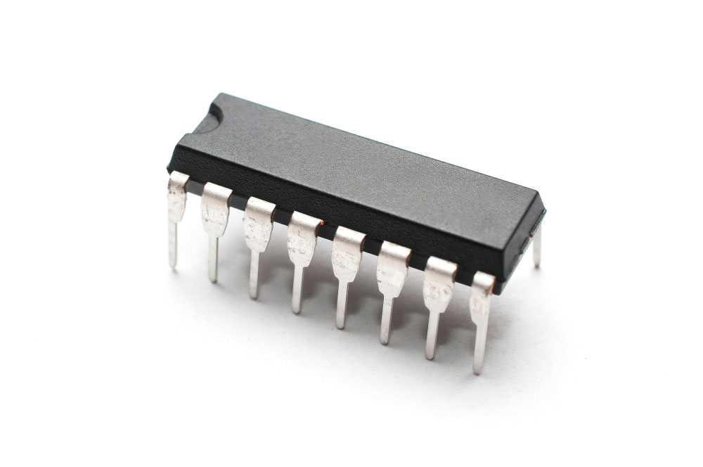
The SPI devices take up less space than their UART microchips, making them ideal for boards with limited space.
SPI vs. UART: Cost
SPI is generally cheaper than UART. However, SPI has more hardware complexity than UART.
SPI vs. UART: Which Should I Choose?
SPI is generally better and more preferred than UART due to its high-speed communication. The serial protocol is better for chip-to-chip links and communication between multiple devices. However, UART is the better option for applications requiring RS-232 support. Also, it is ideal for long-distance communication, such as between diagnostic displays, after conversion to higher voltages.
An RS232 connector
Wrap Up
In conclusion, SPI and UART are two of the most typically used serial communication interfaces in microcontrollers and embedded systems, besides I2C. However, they have some vital differences that define their strengths and weaknesses. And with the comparison above, you should be able to pick the best protocol for your project. That's it for this article. Thank you for reading!
Special Offer: Get $100 off your order!
Please email [email protected] for details.