Unlike a few decades back, today is electronic gadgets continue to shrink in space. Most of them are now smaller and faster.
Addressing Signal Integrity (SI) in today is small-factor circuits pose a significant challenge to designers.
Discontinuities, such as impedance mismatches and sharp bends, among others, affect the signal integrity of digital devices. With such, a circuit becomes unreliable, unstable, and in some cases, even unusable.
So, how can designers avoid such a case? It is simple; through impedance control. This article examines ten ways on how to avoid signal integrity problems by impedance control.
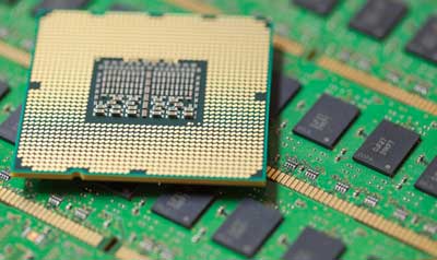
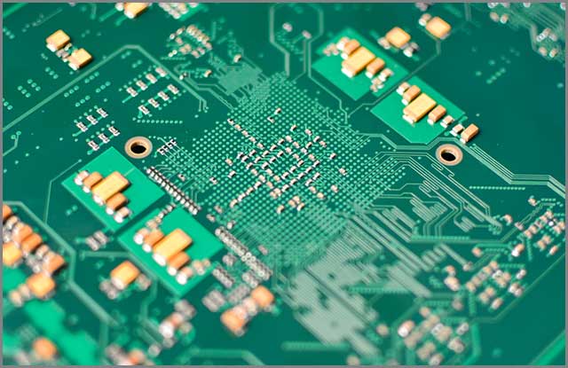
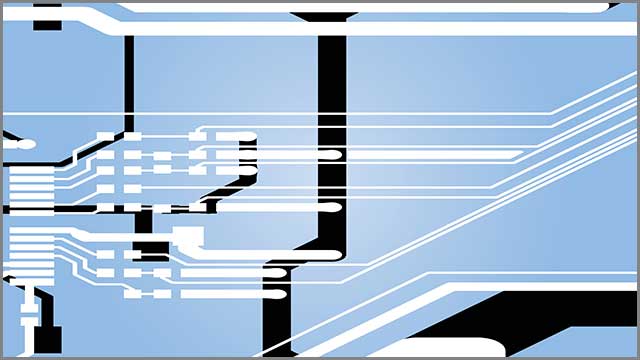
(Control Impendence is a right way of avoiding SI issues)
Contents
- 1.Investing in Termination Resistors
- 2.Maintenance of Same line impedance Throughout a Track length
- 3.Proper Grounding
- 4.Proper Routing
- 5.Use of Low-inductance Traces
- 6.Use of Broader line Spacing
- 7.Applying Differential Routing Technique in Critical Parts
- 8.Use of Short Parallel run Lengths
- 9.Using Short High-speed Signal Traces
- 10.Shielding a PCBs Sensitive Components
- Summary
Special Offer: Get $100 off your order!
Please email [email protected] for details.
1.Investing in Termination Resistors
A terminating resistor is essential when you want to avoid signal integrity problems. Terminating resistors are signal quality components.
Designers use them in soaking up AC signals. They do this to prevent reflections on the line. Unmatched impedance along transmission lines will result in signal integrity problems.
Termination resistors bring about the desired signal integrity. Termination resistors increase performance and speed and reduce intermittent errors. By investing in terminating resistors, designers can do away with a lot of noise. This way, they will be able to improve signal integrity during PCB design.
The main aim of terminating resistors is to improve signal integrity. But, designers need to select the best fit suitable for their applications. Some of them include:
- Parallel Termination、
- RF termination、AC Termination
- Thevenin Termination
- Series Termination
Depending on several forms, designers should select the best termination procedures and resistors. They have to choose those that will result in the desired signals within a circuit.
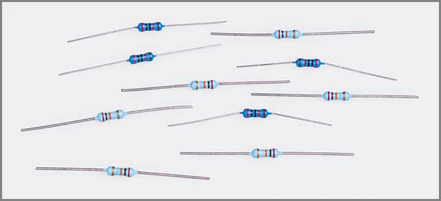
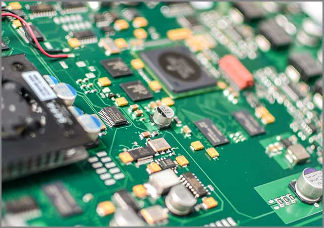
(Investing in the right termination resistors will save you the hassle of SI issues)
2.Maintenance of Same line impedance Throughout a Track length
The capacitance and inductance of a trace within an electrical circuit have several significant impacts. It is especially true at high frequencies. Additionally, transmission lines in a course tend to become a big issue. Such is common when a signal is wavelength is not far away from the trace length. Such may result in scattering and signal reflection. All these are aspects that negatively impact signal integrity.
But to minimize transmission-line effects, it is advisable to ensure the maintenance of the same line impedance. This line impedance needs support throughout the track length. This way, you will ensure that you maintain the values of impedance. With such, you will improve signal integrity.
There are plenty of factors that tend to influence impedance. Chief among them is the distance that exists between the ground plane and the trace. Others include line thickness and a printed circuit board dielectric constant. All these, when ignored, may bring about serious signal integrity problems.
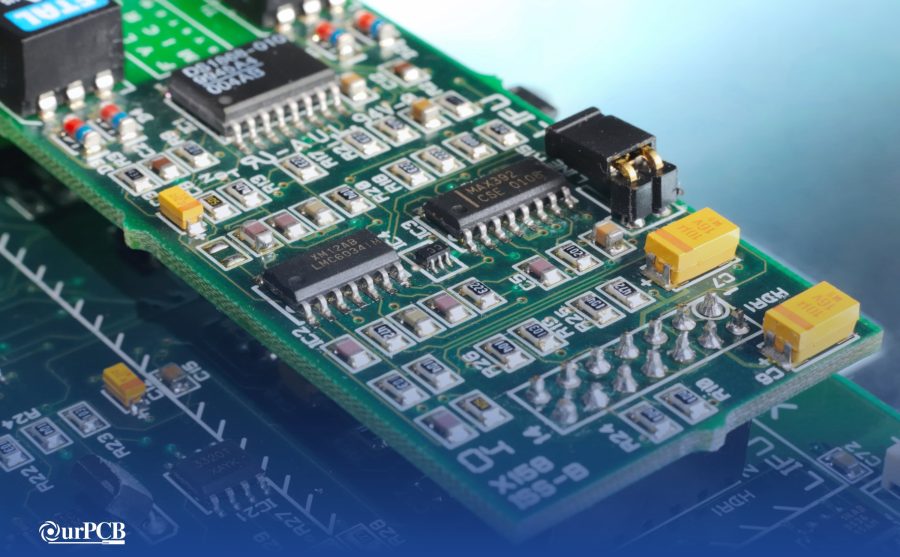
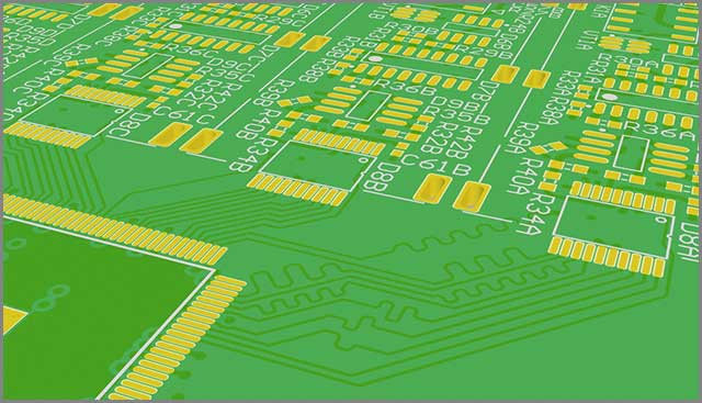
(Same line impedance is a great way to solve SI issues on your PCB)
3.Proper Grounding
Impedance control suggests that circuit designers have to resort to the right grounding techniques to ensure signal integrity. By employing the correct grounding techniques, you will reduce the likelihood of affecting the signal. Grounding techniques include either:
- Arranging components to bring about reliable and short return paths to ground.
- Placing ground and power planes in the layer stack.
Regardless of the method you choose to use, it is essential to ensure proper grounding techniques. With adequate grounding, there is the avoidance of signal integrity problems. In the current active industrial environment, many things interact. They include electrical plant equipment, electronic devices, power wiring, and other process equipment. Such interactions can create noise and electromagnetic interference (EMI) problems.
Proper grounding can significantly help in reducing or eliminating electromagnetic interference or noise. This way, designers maintain the desired signal integrity.
(Every designer needs to have proper grounding techniques to counter signal integrity issues)
4.Proper Routing
Like adequate grounding, the appropriate path is necessary. If designers intend to avoid signal integrity problems, proper routing is essential. When it comes to electronic design, you will often hear of the term routing. Wire routing, also known as routing, is one of the steps when designing printed circuit boards.
Again, routing all the cables in the right way is essential. It is true when you want to do away with signal integrity problems.
Unfortunately, a lot of circuit designers tend to forget this step. For instance, signal cables need routing, away from power sources and all electrical fixtures.
Higher voltages tend to increase electrical noise. Electrical noise is a signal integrity problem for many. For instance, electric motors are not the best choice as they tend to produce some magnetic field. But how far should you route your cables? It all depends on aspects such as the size of the magnetic field and voltage. But you need to do your best to ensure that you do not have a noisy signal through improper routing.
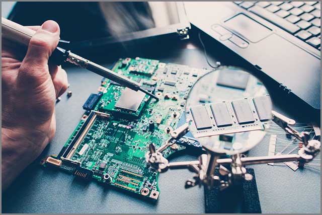
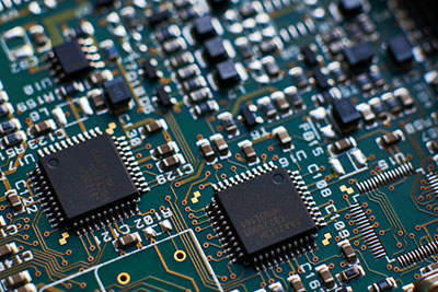
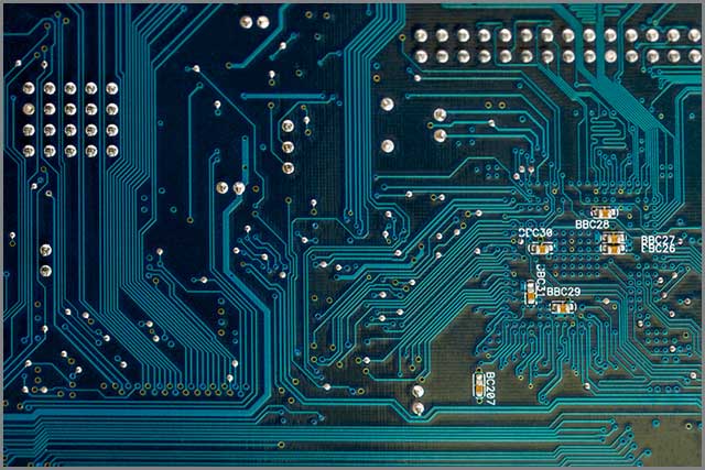
(when it comes to avoiding SI issues, the proper path of your board is crucial)
Special Offer: Get $100 off your order!
Please email [email protected] for details.
5.Use of Low-inductance Traces
Inductors are coils of wires with the ability to store energy in the form of magnetic fields. They also resist alterations in the flow of the current. Depending on where they are going to find their use, there are several types of inductors. There are low-frequency, high-frequency, and power line inductors.
Inductors resist changes of current and act as low-pass filters. They do so when in series with power supply or signal flow. High-frequency inductors are prone to some noise. Noise is undesirable when it comes to ensuring signal integrity. The higher a frequency is, then the grater/larger the impedance will also be. Such ends up suppressing noise and negatively impacting on signal integrity.
Designers intending to avoid signal integrity problems are good with low-inductance traces. Low-frequency inductors are not prone to a lot of noise, unlike high-frequency inductors.
(Having low-inductance traces will ease SI issues by a significant margin)
6.Use of Broader line Spacing
Spacing is vital, regardless of whether it is in your daily living or the circuitry industry. Consider having a noisy neighbor. Will not you somehow prefer to have some more space between yourself and the noisy neighbor? The same is true when it comes to electronic circuits. Line spacing is essential if you want to avoid signal integrity problems.
Spacing is essential to avoid instances of tracking or flashover. Monitoring and flashover may occur between the electric conductors. If you happen to place your wires so close to each other, flashovers and monitoring will occur. Tracking and flashovers will bring about signal integrity problems. Avoiding signal integrity problems requires the separation of parallel traces with considerable space.
(A wider trace width/ line spacing provides enough room to counter SI issues)
7.Applying Differential Routing Technique in Critical Parts
Differential routing is a technique of design used in creating a balanced transmission system. The transmission system can carry differential signals across a circuit. In most cases, differential routing merges to an external transmission system. Transmission systems could be cables or connectors.
There are plenty of advantages that come with differential routing. When going at high speeds, electromagnetic interference and some noise will begin to crop up. Such will degrade the signal. But to ensure the avoidance of signal integrity problems, it is essential to use differential routing. Differential routing is ideal, especially in critical parts of the board.
(The test and use of different routing techniques is an excellent way of finding a routing technique that will solve your SI issues)
8.Use of Short Parallel run Lengths
A parallel length is a distance or height between two edges of metal or any other components. When it comes to matters to do with printed circuit boards, identical run lengths matter a lot. When you have two signals running next to each other, but for a long way, there may be issues to do with signal integrity. Such are problems that you would want to avoid the most.
The reason is that one of the signals may act as the aggressor signal with the other one coming in as the victim signal. But to ensure that you do not compromise on the signal integrity, it is advisable to use short parallel run lengths to avoid problems with signal integrity.
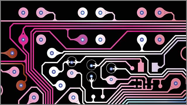
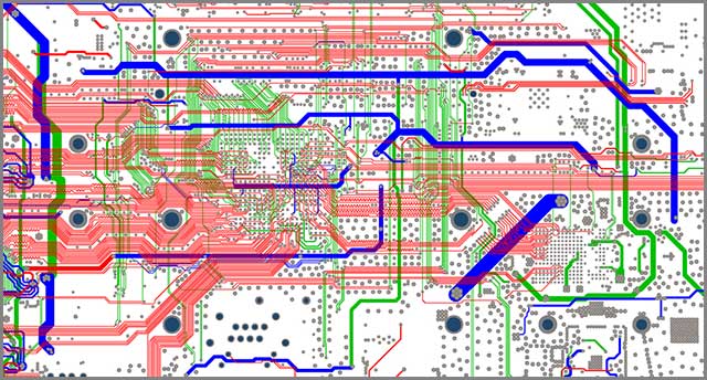
(Short parallel run lengths, as shown above, are also an excellent control impedance technique to address SI issues)
9.Using Short High-speed Signal Traces
As you may be aware, high-speed printed circuit board design often has some problems with EMI. EMI risks emanate from long traces that form receiving or transmitting antennas. More long trails tend to cover a lot of distance. More prolonged traces negatively affect sensitive parts of a circuit, leading to signal integrity problems.
Using shorter high-speed bits with the ability to take direct paths helps to reduce the risks of EMI. Long and winding trails on your circuit can cost you a lot, leading to signal integrity problems. By ensuring that your traces are short, no one will find your designs being unpalatable.
(using shorter high-speed signal traces is a step towards minimizing your SI issues)
10.Shielding a PCBs Sensitive Components
There are several sensitive components that you will find in a printed circuit board. Some of them include high-precision resistors, computer cards, TTL chips, and laser diodes. These are those sensitive components that need some shielding. Lack or poor shielding may .affect sensitive parts of a circuit, an aspect that brings about problems with signal integrity. Shielding sensitive components cut noise and improves signal integrity.
(You need to shield the PCB sensitive parts to ensure that no signal integrity issues come about)
Summary
At last, you will need a reputable manufacturer that will develop your circuits. To get high-quality boards with no integrity issues, then you will have to find a renowned manufacturer. It would help if you had a manufacturer who will communicate everything with you. You need one who'll also offer you other helpful suggestions.
We at OurPCB lead others in the industry when it comes to the manufacture of PCBs. If you desire circuits with no signal integrity problems, contact us. We have been doing this for many years and can get the job done right for the first time. Do you want more information on impedance control? Or how to go about managing printed circuit board signal integrity? Feel free to contact us for help.
Special Offer: Get $100 off your order!
Please email [email protected] for details.