Technicians need a set of tools for building or doing repairs in their respective lines of work. Whether you are an amateur or professional in the field of electronics, one of the most crucial tools to have is a signal injector.
If you are unsure about what this is, we have laid out all the details below. Read more about how the tool works and how to build one, where you will get a list of all the required components (PCBs, transistors, resistors, etc.) for this DIY project.
Contents
What Is A Signal Injector?
As one of the types of a signal generator, a signal injector is an electronic device that produces an electric signal, which you can introduce into the circuitry of an audio receiver.
The purpose of doing this injection is to troubleshoot the source of a problem, in which the issue is a signal or current flow blocking in a circuit. Some of the most common ones include the Micronta signal injector and Eico signal injector.
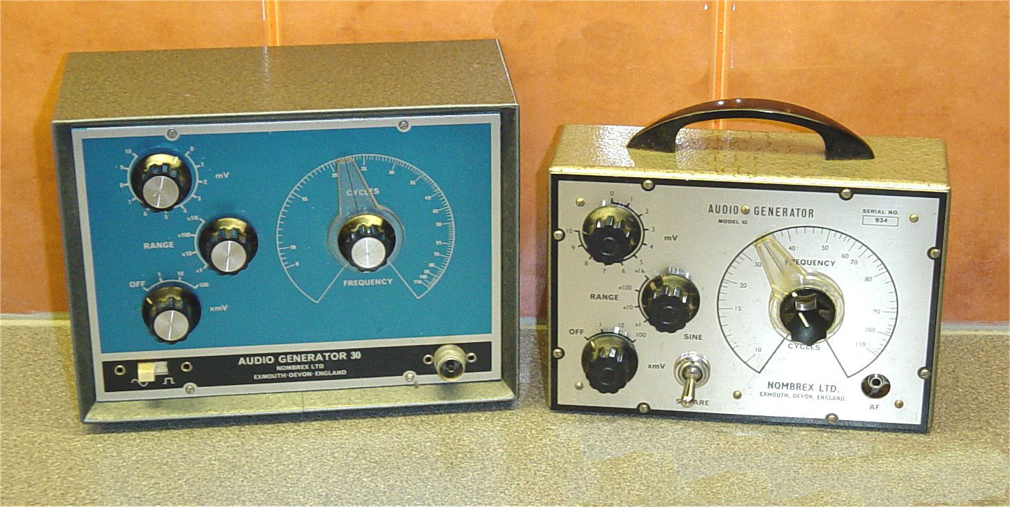
An audio signal generator
Source: Wikimedia Commons.
Special Offer: Get $100 off your order!
Please email [email protected] for details.
How Does A Signal Injector Work?
If your audio system is faulty, you can use a signal injector to introduce an audible frequency range in the volume control.
There are two possible results. If you get an audio signal from the speakers, everything is okay in the audio output stage. However, if you do not get any feedback, then the problem lies in this section.
If everything looks good, proceed with the injection pulse at the preceding RF stage (radio frequency stage), then listen for the output from the speakers.
Continue moving up the stages (intermediate frequency and audio frequency) until there is no output, which will indicate where the problem exists.
Signal Injector Tracer
However, some units combine a signal tracer and injector into one, making them signal injector tracers. These have a tracer probe to pick up the signal, then produce a loud tone because it amplifies it through its circuitry to produce a tunable signal.
In its most simple form, a signal tracer is an amplifier that detects audio and RF signals, then outputs them through its speaker. Some advanced units have a diode detector (usually germanium diodes) to identify amplitude modulation (AM).
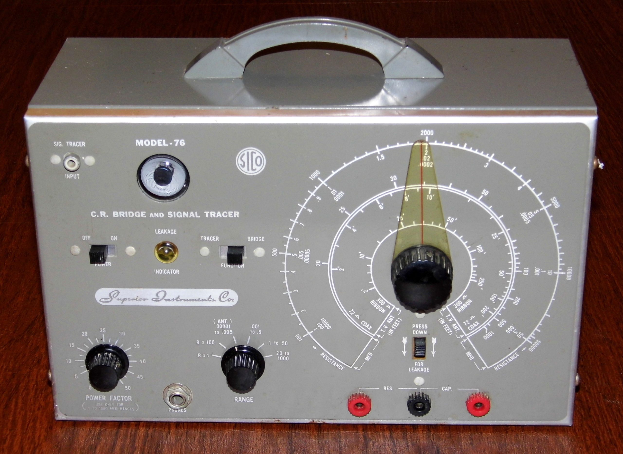
Signal tracer
Source: Wikimedia Commons.
Even though you can use the same AM input signal with frequency modulation (FM) when troubleshooting the radio frequency circuits, you cannot use the diode detector with an FM test signal to test the audio circuits.
Why? Because the component is only sensitive to amplitude modulation.
How To Make Your Own Signal Generator?
You need these components to build a simple circuit signal injector.
- Two 45V 100mA NPN transistors (BC547, BC548, BC549, or 2N3904)
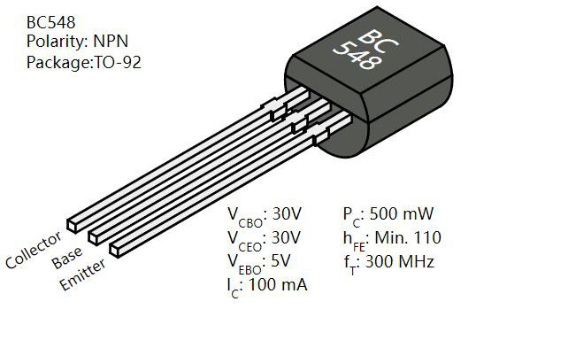
BC548 Transistor
Source: Wikimedia Commons.
- Two 50V 0.015uF ceramic capacitors
- One 25V 10uF electrolytic capacitor
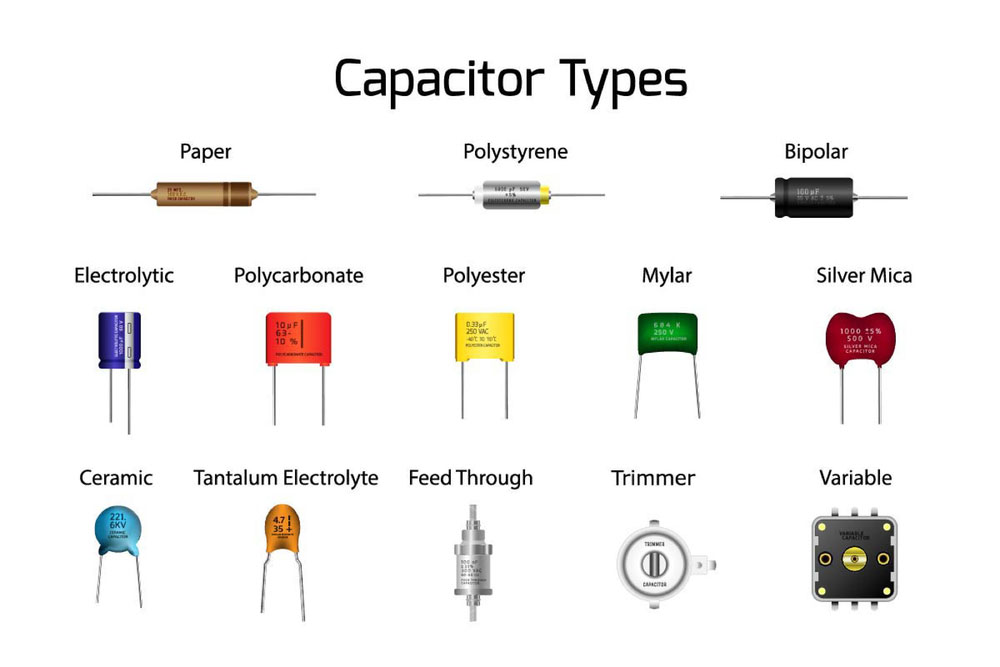
The different types of capacitors
- Two 22k resistors
- One 150k resistor
- One 220k resistor
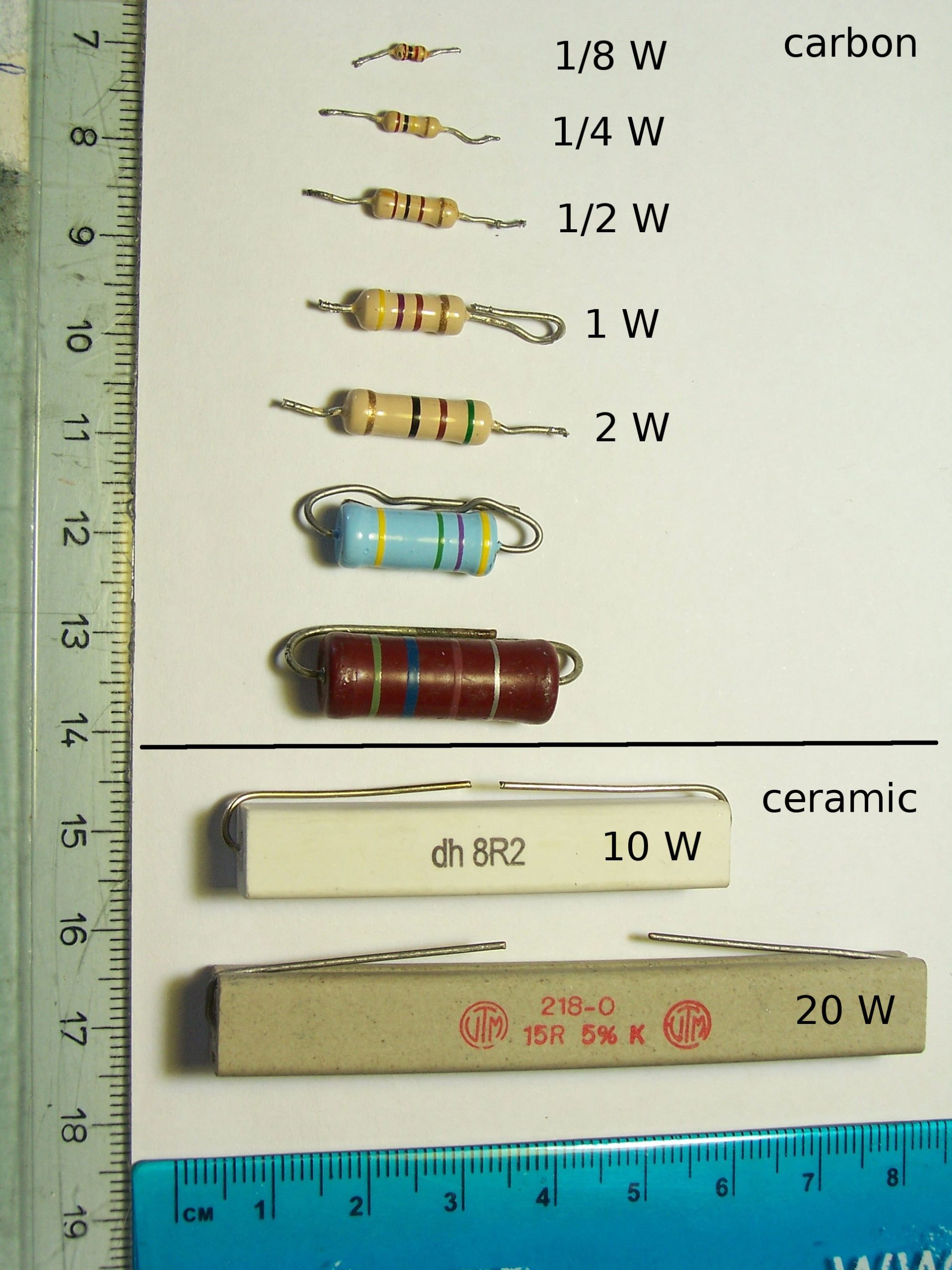
Different resistor sizes
Source: Wikimedia Commons.
- A PCB (a matrix board is also okay)
- One 1.5V battery (AAA) and a battery holder/socket
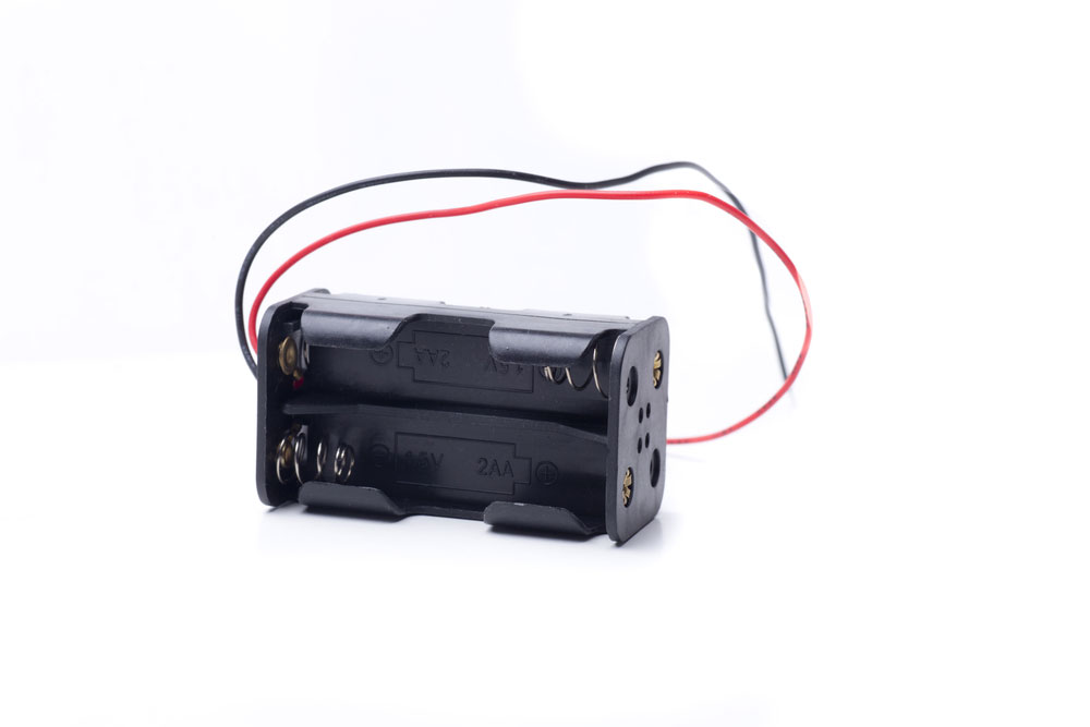
Battery holder
- One alligator clip
- Scope probe
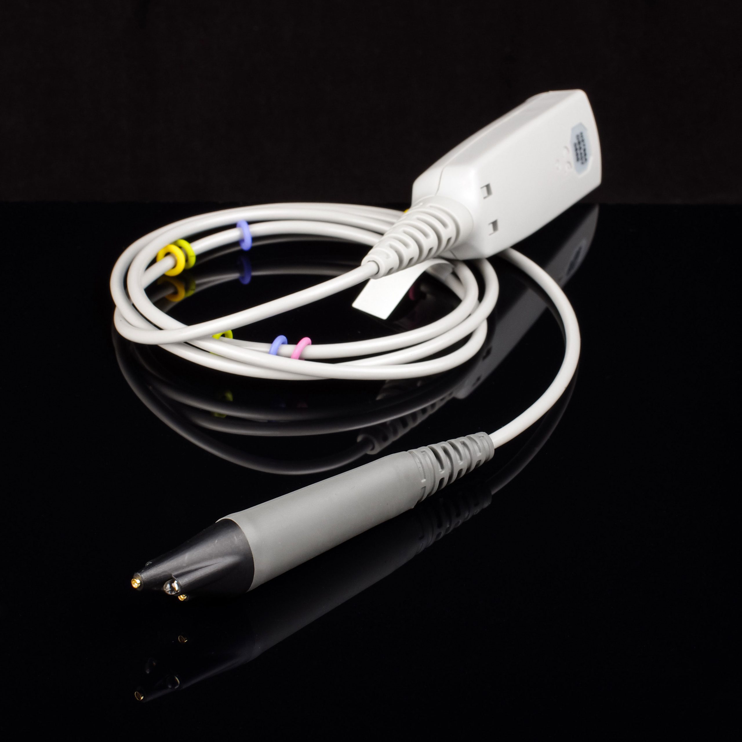
Scope probe
- Thin insulated wire
- One push-button power switch
Injectors have a circuit pattern popularly known as a multivibrator, with two amplifying transistors, three capacitors, and four resistors. The device gets its name from its output waveform, which is rich in harmonics.
The most common type used for pulse injection is the astable multivibrator. It features an unstable circuit that switches to different states continuously, producing a square or triangular wave, just like a relaxation oscillator.
Board Layout
The components layout on the board is key to building an injector with minimal errors.
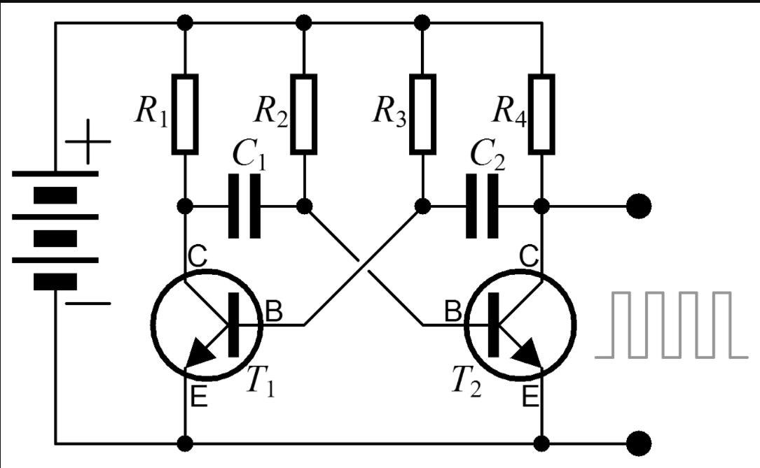
Astable multivibrator circuit diagram
Source: Wikimedia Commons.
Following the mechanical layout above, first set up the resistors by soldering them on the PCB or mounting them on the matrix board in a low-profile, almost flat position.
Next, fit in the capacitors, and place the electrolytic capacitor just before the probe (after the R4, C2, and T2 joint). Finish off by installing the two transistors, which are the main components in the circuit.
Circuit Connection
Connect the resistor lead-out wires in this configuration.
- R1 to C1 to the collector lead of T1
- R2 to C1 to the base lead of T2
- R3 to C2 to the base lead of T1
- R4 to C2 to C3 to the collector lead of T2
- C3 to probe lead
Battery Connection
Once you have set up all these nine external components on the board, hook up the battery holder to all the resistor top leads. If using a matrix board, connect the ends of these resistors on the underside using the uninsulated wire, then solder the battery socket’s red wire to one end of the joined resistors.
Next, connect the emitter leads of both transistors to the black wire of the battery holder. Place the push button power switch somewhere between the battery and the transistors.
Also, run the ground wire to these emitter leads to complete the circuit. Attach the alligator ground clip to the end of the ground wire for easy earthing.
You can use AAA, rechargeable batteries (li-ion batteries), or any DC source that matches the required battery output voltage (1.5V).
Test the Injector
If you have built the simple signal injector circuit described above, then you have created what is essentially a noise generator that spews an audio tone out of the probe in random frequencies.
The goal is to begin connecting the probe to the radio’s grid at the output stage (speaker), then go back towards the ferrite rod antenna one step at a time while listening for some noise or tone from the speakers.
Since it produces the audio tone in different frequencies, you can also call your custom-made injector a white noise generator or pink noise generator (uniform octave band).
Summary
As you can see, signal injectors are critical troubleshooting tools for electronic technicians when repairing audio equipment.
Instead of buying an expensive ready-made unit, you can assemble one yourself using the diagram and procedure above.
If you have any inquiries or do not know how to get the components to build a signal injector, contact us for more information.
Special Offer: Get $100 off your order!
Please email [email protected] for details.