Knowing how much power you consume in your home is critical for data visualization and analytics. CT sensors can measure the alternating or direct current running through a circuit to give you the required data.
The DC measurement part can be contentious but doable with a few tweaks in the CT sensor design.
Let’s look at how this device works and the factors to consider when installing one in your electrical circuit.
Contents
Special Offer: Get $100 off your order!
Please email [email protected] for details.
What Is a CT Sensor?
Also known as current sensors, current transformer (CT) sensors are devices that traditionally measure only the alternating current flow of electrons.
We’ll look at the DC part later. The device measures electric flow using the magnetic field generated around the conductor.
How a CT Sensor Works
CT sensors have a primary winding, magnetic core, and secondary winding, just like transformers.
Some have split magnetic cores to allow clipping onto live or neutral wires without having to cut or modify the electrical lines, while others have solid ring cores.
The primary winding detects the magnetic field of the current because it sits near the opening where the live or neutral wire runs through.
It converts this field into alternating current, producing a magnetic field in the core.
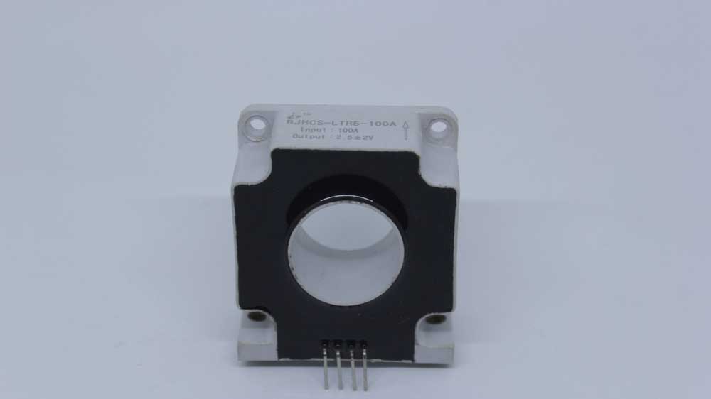
A current transformer sensor
This field induces an alternating current in the secondary winding that is proportional to the primary circuit current.
Structurally, the secondary winding has zero metal contact with the primary circuit because the two are galvanically isolated.
The sensor must have a burden resistor to complete or close the secondary winding circuit to keep the voltage in check.
However, this resistor’s value must be low enough to prevent magnetic core saturation.
What About DC Detection?
As stated earlier, CT sensors traditionally detect alternating current. Transformers cannot work with DC because the current lacks a changing magnetic field.
Technically, the transformer can detect direct current, but the magnetic core will saturate quickly, losing the measuring capability.
If you find a way to reset this flux to avoid saturation, it becomes possible to measure direct current.
Some solutions include installing a tertiary coil around the core to create a hall-effect sensor-like design. But this method has its inaccuracies.
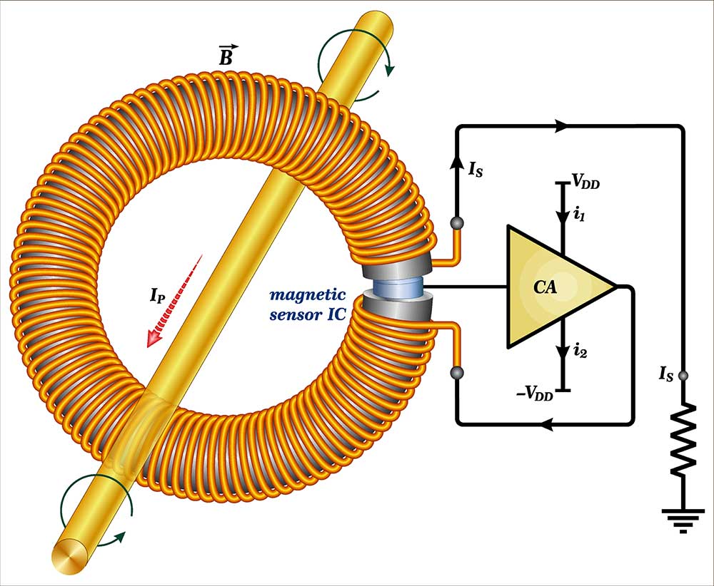
A closed-loop hall-effect current transformer
Some proprietary technologies are more precise because they eliminate the air gap associated with hall effect sensors.
This design makes the CT sensor more sensitive and immune to external magnetic fields, resulting in high-precision DC sensor measurements.
Special Offer: Get $100 off your order!
Please email [email protected] for details.
CT Sensor Safety
You must never open-circuit the secondary circuit of a CT sensor after connecting or clamping the device around the current-carrying conductor.
Open circuiting will make the secondary circuit continue driving the induced current from the primary winding to an infinite impedance.
The result will be a dangerously high voltage across the secondary terminal contacts.
Therefore, you should use a burden resistor to close this circuit. Some CT sensors come with built-in Zener diodes as protection features.
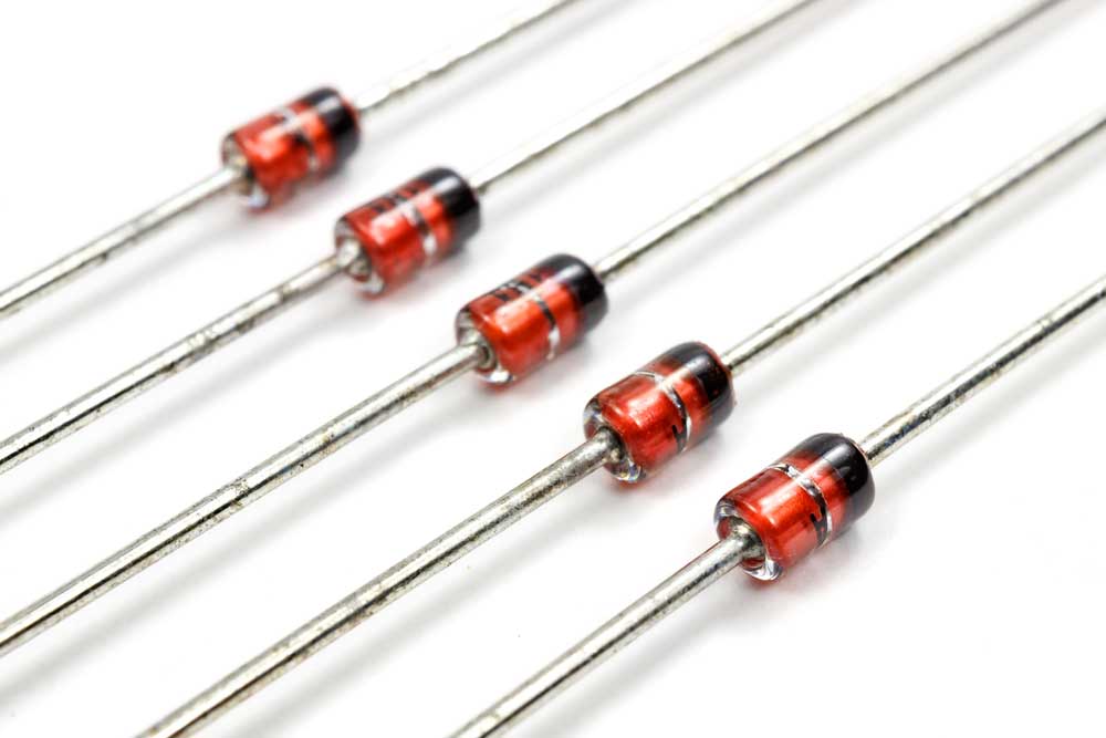
A set of Zener diodes
How To Install a CT Sensor
These two factors are critical when installing CT sensors.
Wrap Around Only One Conductor
The CT sensor’s primary winding should wrap around the current-carrying conductor whose current you want to measure.
And remember, the CT sensor measures the alternating or changing magnetic field.
Therefore, you must clamp or fit the split-core CT sensor around a conductor with one core.
Wrapping it around two or three-core wires transmitting electric current in opposite directions will lead to inaccuracies.
The magnetic fields can even cancel each other, resulting in zero output.
If handling a 3-core wire, we recommend using a 3-channel CT clamp sensor, which can measure the electric current on all three conductors concurrently.
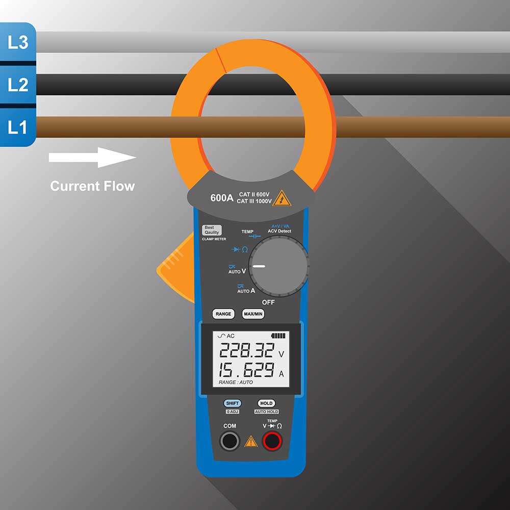
A current clamp meter in a three-phase conductor setup (note it only wraps around a single conductor)
You’ll have to separate the conductors and place them in the three clamps, but you’ll only have to buy one device instead of three.
Make the Wrapping Loose
The ferrite or magnetic cores in CT sensors are brittle pieces of hardware.
You can break them if you clamp the split-core device firmly around the conductor (with packing material).
If using a ring core current sensor option, only insert it into a cable that passes through the hole freely.
If you force the cable through, you can break the brittle core, making the sensor useless.
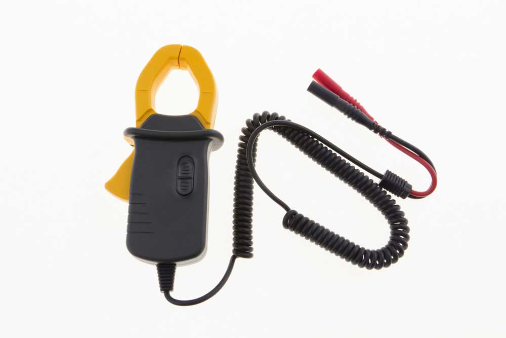
A current clamp for measuring electric current flow
However, the orientation and position of the electric conductor in the CT sensor aperture do not affect the output reading.
CT Sensor Technology Applications
Since CT sensors measure the electrical current flowing in the circuit, they are critical in indicating the power consumption level. They are more common in AC applications in the following areas.
- Utility submetering when dealing with multiple tenants
- Facility power regulation to increase efficiency and reduce operating costs
- Home energy monitor
- Spotting flaws like irregular electric current flow through electrical devices
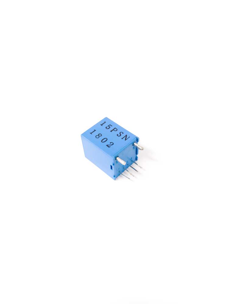
A DC sensor
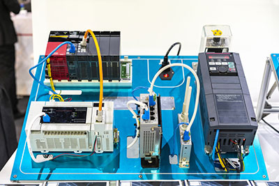
These sensors are also critical for IoT applications, where they can help you monitor electric power generation or consumption in real-time in these areas.
- Solar/wind power generation (smart grids)
- Monitoring power-driven equipment
- Keeping track of consumption costs to optimize systems and keep bills low
- Monitoring workplace safety
You only have to equip these sensors with transmission technology like Bluetooth or LoRa wireless communication technology to get real-time current sensor data.
This data can help you change power consumption behavior or rectify leakages/irregularities to lower power bills.
Wrap Up
CT sensors are critical devices in modern power systems because they help visualize energy consumption data.
This data indicates trends in electric power consumption to help optimize and reduce power bills.
And you extend the transformer’s capabilities to deliver data in real-time for IoT projects.
We can help you assemble this sensor for your circuit board. Contact us with your details to get started.
Special Offer: Get $100 off your order!
Please email [email protected] for details.