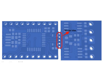
RJ45 pinouts, also known as 8P8C connectors, are modular connectors used for Ethernet cables in devices like computers, routers, and switches. The “RJ” stands for registered jack, and “45” denotes the specific interface standard.
These connectors feature eight pins, each of which plays a specific role in sending and receiving data signals between devices. Each wire in an RJ45 pinout must be placed correctly according to recognized standards for proper data transmission.
If the pinout of RJ45 isn’t wired correctly (according to the RJ45 connector wiring diagram) it can lead to network failures, connectivity issues, and slower data transfer speeds. This will impact network performance and reliability.
Contents
- What are the Main RJ Pinout Standards?
- T568B
- T568A
- T568A vs. T568B: What's the Difference?
- What is the Wiring Procedure for RJ Connectors?
- What are the Different Types of Ethernet Cables?
- Straight-Through Cables
- Crossover Cables
- Why is it Important to have Correct RJ45 Pinouts?
- Network Functionality
- Maintaining Signal Integrity
- Preventing Electrical Issues
- What are some other RJ Cable Types?
- RJ11
- RJ12
- RJ14
- RJ25
- RJ48
- What Standards and Applications Involve RJ Connectors?
- TIA / EIA-568 Series
- TIA-1096
- IEEE 802.3
- IEEE 802.3ab
- IEEE 802.3af and IEEE 802.3at
- How can Existing RJ Cables be Tested and Verified?
- What Cable Categories and Shielding Options are Available for RJ Connectors?
- Cable Categories for RJ Connectors
- Shielding Options
Special Offer: Get $100 off your order!
Please email [email protected] for details.
What are the Main RJ Pinout Standards?
There are two primary RJ45 wiring standards: T568A and T568B. These two standards define the RJ45 connector diagram, or the order in which the wires are arranged, within twisted-pair cabling used in networking.
T568B
This is the standard wiring scheme for twisted-pair structured cabling in the U.S. and is widely adopted for commercial installations. T568B wiring offers better signal isolation and noise protection, which is why it has become the preferred choice, especially for applications that require higher data transfer rates.
T568A
This standard is less commonly used today, but it was prevalent in older installations. It is often used in federal government installations and by certain organizations that follow specific cabling guidelines.
T568A vs. T568B: What's the Difference?


The only difference between T568A and T568B is the order of the colored wire pairs within the cable. The order of the connected wires does not affect speed, as they are still straight or direct connections.
| Pin Number | T568A Wire Color | T568B Wire Color |
| Pin 1 | White/Green | White/Orange |
| Pin 2 | Green | Orange |
| Pin 3 | White/Orange | White/Green |
| Pin 4 | Blue | Blue |
| Pin 5 | White/Blue | White/Blue |
| Pin 6 | Orange | Green |
| Pin 7 | White/Brown | White/Brown |
| Pin 8 | Brown | Brown |
What is the Wiring Procedure for RJ Connectors?
1. Prepare the Cable
- Strip about 1 inch (2.54 cm) of the outer jacket from the cable end using a stripper tool. Be careful not to damage the internal wires.
- Untwist the pairs of wires and arrange them in the correct order according to the chosen standard.
- Flatten and straighten the wires. Make sure they are parallel.
- Trim the wires so they are even and protrude slightly from the end of the jacket.
2. Insert Wires into Connector
- Hold the RJ45 connector with the clip facing down and the gold contacts facing up.
- Carefully insert the wires, ensuring each wire slides into its designated channel and makes contact with the gold pin at the end. The wire insulation should be flush with the end of the connector.
3. Check and Confirm Your Wire Order
- Double-check that the RJ45 pinout order matches your chosen standard (T568A or T568B).
4. Crimp the Connector
- Place the connector into the crimping tool, and ensure it is seated correctly.
- Firmly squeeze the handles of the crimping tool until they click or bottom out. This action cuts off excess wire and secures the connection.
5. Test the Connection
- If you have a cable tester, use it to verify that the crimped connection is working properly.
What are the Different Types of Ethernet Cables?
There are two different types of RJ45 cables based on wiring configuration: straight-through cables and crossover cables. The wiring setup determines which devices it can connect.

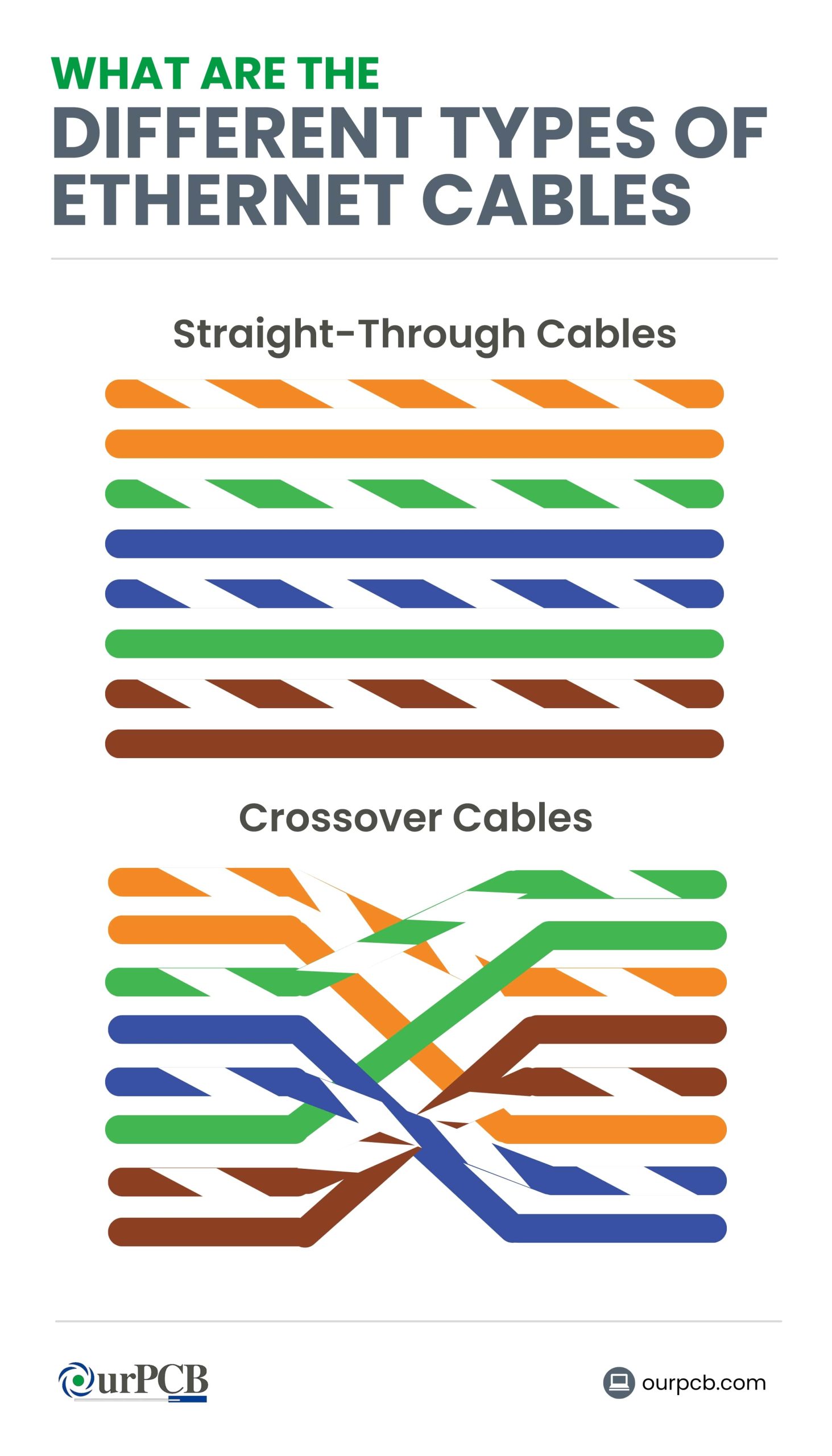
Straight-Through Cables
Straight-through cables have a specific wiring configuration, with each end using a different wiring standard. One end uses T568A standard, while the other end follows the T568B standard.
This means the transmit pins on one end are connected to the receive pins on the other end, and vice versa. This straight-through pinout setup ensures that the transmit (TX) and receive (RX) signal pairs are properly aligned. These cables are used to connect two different types of network devices for data communication.
Crossover Cables
This kind of cable is used to interconnect two devices of the same type directly, e.g., two computers, two switches, or two routers. One end of the cable uses the T568A standard, while T568B is used on the other end.
This crosses the TX and RX pairs, so one end connects to the receive pair on the other end, and vice versa. Use a crossover cable for direct communication between the same types of devices by internally crossing the signal pairs.
Special Offer: Get $100 off your order!
Please email [email protected] for details.
Why is it Important to have Correct RJ45 Pinouts?
Network Functionality
The pinout is a specific arrangement of wires within an RJ45 connector, which determines how devices communicate. The transmit pins on one device need to connect to the receive pins on the other for data to flow correctly.
If the RJ45 pinout is incorrect, the devices won’t be able to understand each other’s signals, leading to a loss of connectivity. Proper RJ45 pinning prevents issues like no connection, intermittent connectivity, and signal degradation. This ensures a stable and reliable network.
Maintaining Signal Integrity
Twisted pairs help minimize electromagnetic interference. However, if the RJ45 pinout is wrong, the twist patterns might be disrupted, leading to crosstalk and signal degradation. This can result in slower speeds, packet loss, and intermittent disconnections.
Preventing Electrical Issues
Incorrect pinouts can result in short circuits or reverse polarity, potentially damaging the network interface cards (NICs) in your devices or other connected hardware. This is especially true if you’re using Power over Ethernet (PoE), which sends electrical power through the Ethernet cable, as incorrect wiring could lead to power surges or insufficient power delivery.
What are some other RJ Cable Types?

RJ45 connectors are best known for Ethernet networking, other RJ cable types are used for various purposes, particularly in telecommunications.
RJ11
RJ11 is a 6-position, 2-conductor (6P2C) connector commonly used in telephone wiring. It connects landline telephones to wall outlets and is also used in modems and fax machines. It can support single-line telephones, ADSL, and LAN connections.
RJ12
RJ12 is a 6-position, 6-conductor (6P6C) connector, similar in size to RJ11 but with all six positions wired. It’s mainly used in office phone systems and Private Branch Exchange (PBX) systems, which require additional lines for features like multiple phone lines and intercoms.
RJ14
RJ14 is a 6-position, 4-conductor (6P4C) connector used for 2-line telephone systems. It allows the connection of two separate phone lines within a single connector and is common in residential and small business settings where they require multiple phone lines.
RJ25
RJ25 is a 6-position, 6-conductor (6P6C) connector used to connect three telephone lines. It’s used in complex telecommunication systems that require multiple lines, such as in large office environments.
RJ48
RJ48 is an 8-position, 8-conductor (8P8C) connector similar to RJ45 but designed for T1 and ISDN telecommunications. It’s used for digital signal transmission and provides a reliable way of connecting high-speed data services, often found in professional networking environments.
What Standards and Applications Involve RJ Connectors?
TIA / EIA-568 Series
EIA-568 was the original designation for the telecommunications cabling standard developed by the Electronic Industries Alliance (EIA). However, the EIA has since been dissolved, and the responsibility for the standard was transferred to the Telecommunications Industry Association (TIA) and accredited by the American National Standards Institute (ANSI).
This is the standard for commercial building telecommunications cabling infrastructure, including RJ45 connectors. It defines various categories of twisted-pair cables (e.g., Cat 5 Ethernet pinout, Cat 6) and specifies wiring configurations for structured cabling systems.
TIA-1096
This specification covers the mechanical and electrical characteristics of RJ45 connectors for Ethernet applications. It outlines requirements for dimensions, materials, and performance to ensure compatibility and reliability in networking equipment.
This specification focuses on the mechanical and electrical requirements for RJ45 connectors used in Ethernet applications, and it ensures compatibility and reliability.
IEEE 802.3
IEEE 802.3 defines Ethernet standards, including specifications for physical layer components such as cables and connectors. While it doesn’t directly specify RJ connectors, it establishes the electrical and physical characteristics of Ethernet connections, often using RJ45 connectors.
IEEE 802.3ab
IEEE 802.3ab specifies Gigabit Ethernet over twisted pair cabling, including the use of RJ45 connectors. It outlines requirements for cables and connectors (Cat5 pin assignment, Cat6 pinout, etc.) to support Gigabit Ethernet speeds.
IEEE 802.3af and IEEE 802.3at
These standards define PoE technologies, which often utilize RJ45 connectors for both data and power transmission.
How can Existing RJ Cables be Tested and Verified?
- Basic Continuity Tester: Used to check if all wires are connected, but it doesn’t detect complex issues like crossed wires or the quality of the connection.
- Advanced Cable Tester: Provides more detailed information, including wire map, length measurement, and signal strength. This tool can diagnose more complex wiring issues.
- Network Application Testing Tools: Connect the cable to network devices and monitor for errors or slow speeds, providing a real-world test of the cable’s performance.
- Visual Inspection: Involves looking for broken connectors, frayed wires, or bent pins. This simple first step can catch obvious problems.
- Time Domain Reflectometer (TDR): This specialized tool sends electrical pulses down the cable and measures the reflections to pinpoint the exact location of any faults, such as breaks or shorts, within long cable runs.
- Certification Tester: A professional-grade tool that performs a comprehensive set of tests to verify that the cable meets industry standards and can support specific network speeds (e.g., 1000BASE-T, 10GBASE-T).
What Cable Categories and Shielding Options are Available for RJ Connectors?
Cable Categories for RJ Connectors
- Cat 5e: Supports up to 1 Gbps, 100 MHz, common in homes and small offices
- Cat6 Cable: Supports up to 10 Gbps (55 m), 250 MHz, used in high-speed computer networks
- Cat6a: Supports 10 Gbps (100 m), 500 MHz, enhanced performance
- Cat 7: Supports up to 10 Gbps, 600 MHz, shielded for better EMI protection
- Cat8: Supports up to 40 Gbps, 2000 MHz, used in data centers
Shielding Options
- UTP (Unshielded Twisted Pair): Cost-effective, suitable for most environments
- STP (Shielded Twisted Pair): Extra shielding, better in high interference areas
- FTP (Foiled Twisted Pair): Each pair wrapped in foil, has higher EMI protection
- S/FTP (Screened Fully Shielded Twisted Pair): Combines foil and braided shielding for maximum EMI protection
Back to top: RJ45 Pinouts Explained
Special Offer: Get $100 off your order!
Please email [email protected] for details.