For budding engineers, hobbyists, and anyone interested in electronics, a battery charge circuit can be one of the most worthwhile projects to undertake. Whether batteries for LEDs, smartphones, or other electronic devices, As such, it is impossible to go a day without using a battery-operated device. Different batteries require different charging options.
Essentially, it means that if you already have a battery charge circuit, you will want to customize it to suit your specific battery charging requirements. Thus, that is what the following guide aims to do. In it, we will cover the factors you’ll need to pay attention to when customizing your charge circuit, as well as common customization functions.
Contents
- Battery Charge Customization Factors
- Nickel metal hydride batteries
- Nickel cadmium batteries
- Lithium-ion polymer batteries
- Sealed Lead Acid Batteries
- Common Battery Charge Circuit Configurations
- 12V Constant Voltage Battery Charger
- Nickel-Cadmium Battery Charger
- 12V Battery Absorb and Float Charge Circuit
- Fast Lead Acid Battery Charger Circuit
- High Current Li-Ion Charger Circuit
- Conclusion
Special Offer: Get $100 off your order!
Please email [email protected] for details.
Special Offer: Get $100 off your order!
Please email [email protected] for details.
Battery Charge Customization Factors
There are different types of commercial rechargeable batteries. However, the most common include nickel-metal hydride (NiMH), nickel-cadmium (NiCd), lithium-ion polymer (LiPo), lead-acid and rechargeable alkaline batteries.
It would be best to take special precautions to construct or customize your charge circuit for each battery type. Thus, iIn this section of the guide, we’ll be covering the factors that may influence how your charge circuit will work for each battery type.
-
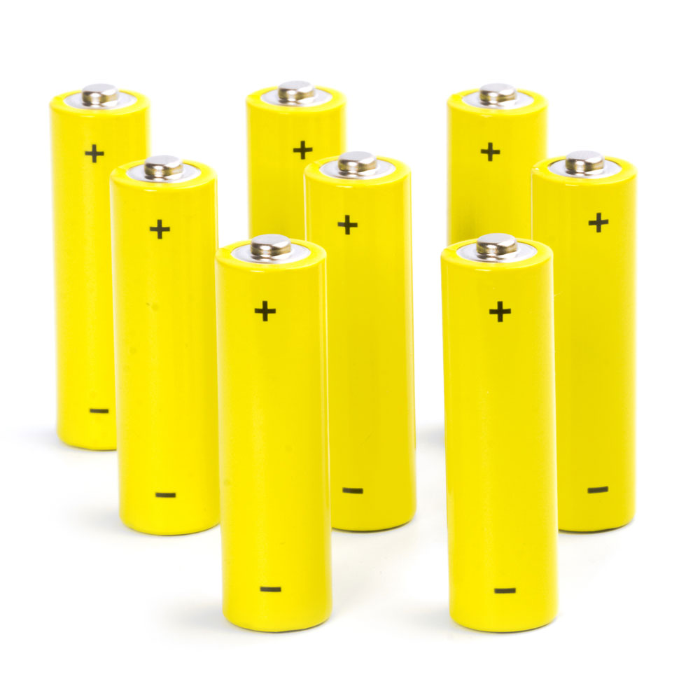
Nickel metal hydride batteries
Nickel-metal hydride big ultra long-life battery isolated
-
- Current regulated charging: A set of transistors, resistors, and switches need to regulate the maximum current to help prevent any overcharging.
- Battery leakage: Special precautions need to be taken against overcharging as this may cause battery leakages.
- Battery position: Reversing the terminals on the battery may cause the batteries to discharge or act irregularly.
- Charge cycle: On average, nickel-metal hydride batteries have a limit of up to 500 recharge cycles.
-
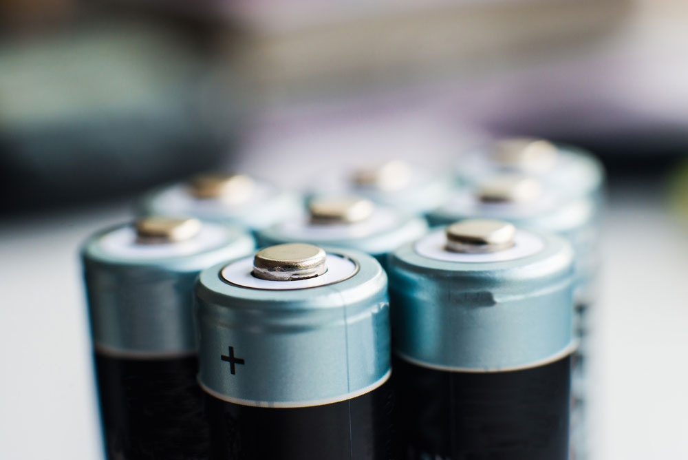
Nickel cadmium batteries
 Nickel Cadmium batteries which are rechargeable
-
- Constant current: The best way to charge a NiCad battery is using a constant charge current. Therefore, if you’re going to charge a single 500 mAh AA battery, we suggest you use a constant bulk charge rate below 50 mA.
- Charge cycles: NiCad batteries have a limit of up to 1000 charge and discharge cycles.
-
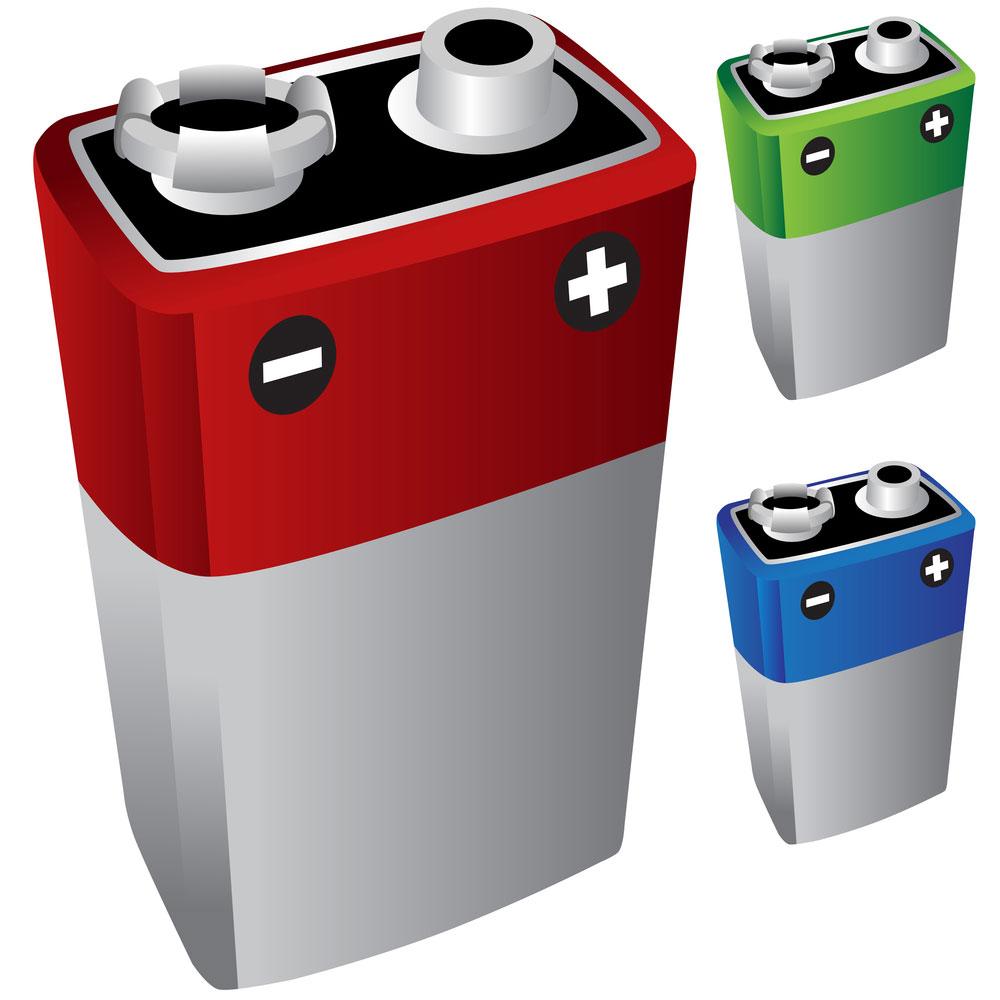
Lithium-ion polymer batteries
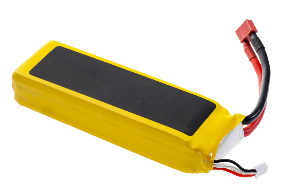 Lithium-ion polymer battery
-
- Step Charging: Lithium-ion polymer batteries are less resistant to over-charging. While in most cases, you can and should use a constant current to charge them, you can employ a step charging method for safety and longevity. Furthermore, you can achieve this through a series of resistors that reduce the intensity of the current in different phases.
- Thermal management: Li-ion batteries are popular for their fast-charging capabilities. Consequently, smartphone manufacturers primarily use them in their devices. However, when charging them, you do need to pay attention to battery temperatures. You can manage this by integrating a heatsink into your charger design. Accordingly, battery temperature monitoring is important for any Li-ion battery. High temperatures may lower the overall battery life.
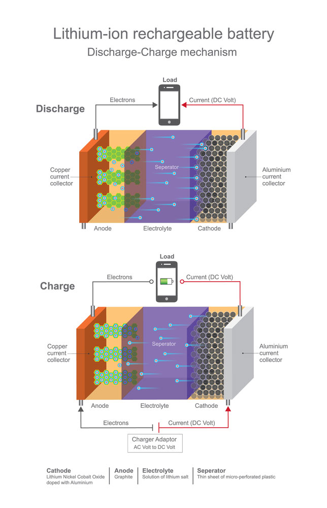 Stock illustration of lithium ion rechargeable battery
-
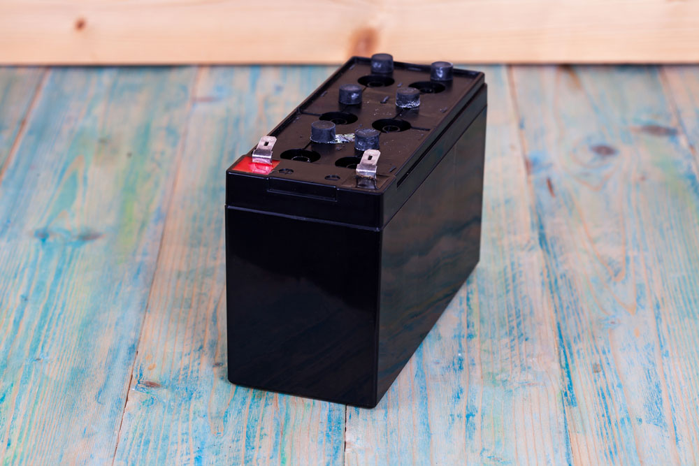
Sealed Lead Acid Batteries
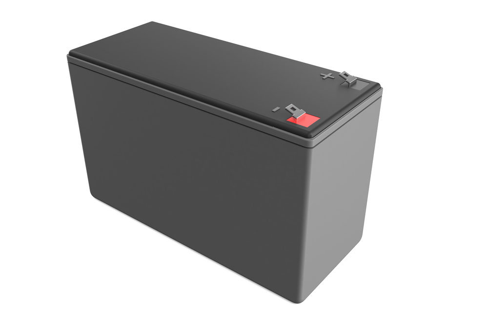 lead-acid battery
-
- Constant Voltage: We charge sealed lead acid batteries using the constant voltage method.
- Constant Current: We charge the sealed lead acid battery using a constant current until it reaches a certain amount of voltage, then we trickle-charge it. As such, you will need to build or alter your charge circuit accordingly.
- Auto-cut-off: To prevent overcharging, we must integrate an auto-cut-off mechanism.
Common Battery Charge Circuit Configurations
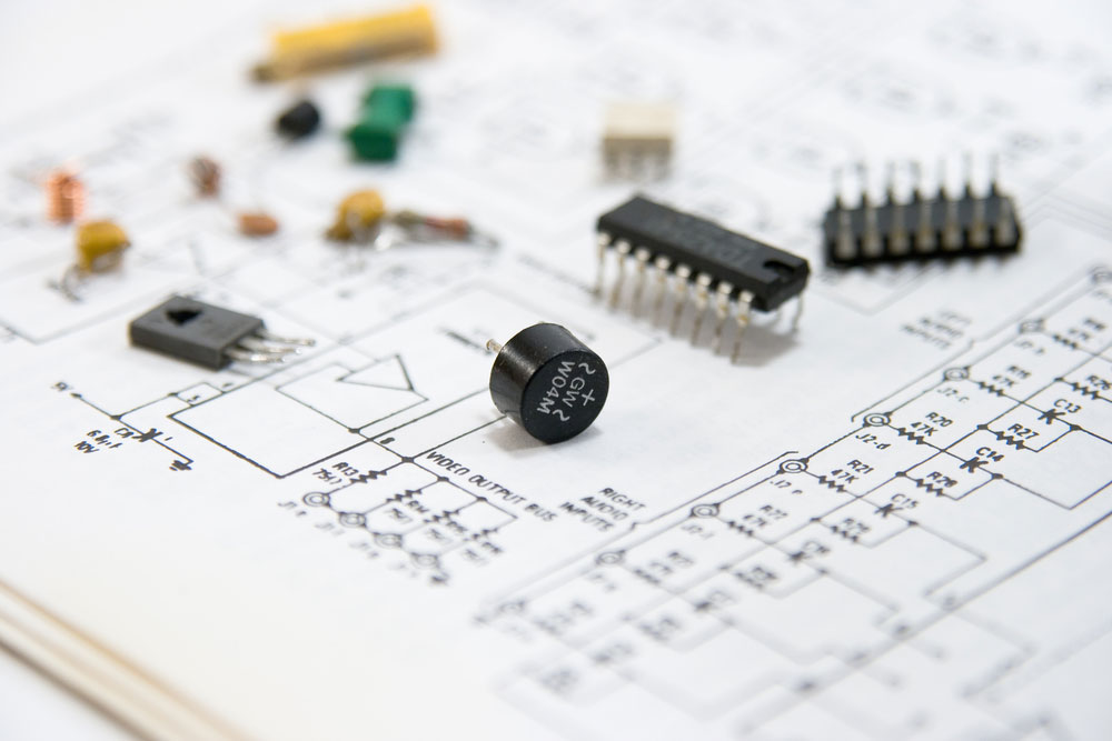 Electronic components spread out on a circuit diagram
In this section of the guide, we’ll cover various battery charge circuit functions and configurations. We will go over the parts and principles for each.
12V Constant Voltage Battery Charger
Parts List
To create your constant battery charge circuit for a 12V 100 Ah Battery, you’ll need:
-
- 10kΩ Resistor x 2 (R1 and R2)
- 1KΩ Resistor (R3)
- 6KΩ Resistor (R4)
- 12Ω Resistor x 2 (R5 and R6)
- 1nF Capacitor (C1)
- 220µF Capacitor (C2)
- 1N4001 Diode (D1)
- 1N4148 Diode x 2 (D2 and D3)
- Green LED (D4)
- BD140 Transistor (T1)
- BC546 Transistor (T2)
- 18V Transformer
Principle
The constant voltage charger is a simple charger circuit to design, construct and ultimately customize. We commonly use them in sealed lead acid batteries for cars. Ordinarily, they consist of a constant power supply (DC) that may comprise a step-down transformer and a rectifier. If you plan on using a constant voltage charger on a lithium-ion polymer battery, you’ll require a more advanced design.
You can use the above constant voltage battery charger to charge a single battery or multiple batteries. However, they need to have a combined voltage of 12V. As such, you can use it to charge a total of six 2-volt batteries.
The above design is compact enough for you to package it into a network adapter. It’s also hard to use incorrectly. Conversely, even if you connected the batteries with reverse polarity, it would not short-circuit or affect the circuit. This battery charge circuit uses a green LED light as an indicator.
It uses a secondary circuit with a 1N4001 diode bridge to rectify an 18V alternating current which a transformer supplies. A 6mA current will run through the circuit and charge your discharged battery. It will go through from R2 to D2 and then R4 to R6 until it reaches D1.
Once the battery(s) has reached 0.5 volts, the first transistor’s base-emitter will be saturated enough to bring it into conduction. Overall, a 500 mAh NiCD battery will take 12 hours to charge fully. The T1 transistor will prevent it from short-circuiting.
Nickel-Cadmium Battery Charger
Nickel-Cadmium Batteries
Parts List
- 0-6 6V 500mA Step Down Transformer
- Mains power cable with 230V AC Power Input
- 1N4007 PN junction rectifier diode
- Resistor 10Ω x 2
- Green LED
Principle
If you find the previous battery charge circuit customizations a little too challenging to build, here is a more straightforward design. It’s a simple metal nickel-cadmium battery charger that requires fewer parts than the previous base design. In fact, all you need is a total of six components.
You can use it to recharge your mobile phone battery and rechargeable torch. In this project, we advise that you use two AA-sized batteries. You can also use the above battery charge circuit to charge dry cell batteries.
The above circuit is a slow charger. Thus, it will ensure the lifespan of your battery. Furthermore, it will take 12 hours to charge your batteries fully. The circuit uses a 220V alternating current that goes through a 0-6V step-down transformer. Next, the circuit carries the current to the 4007 diodes and passes it through to the 10-ohm resistor before reaching a secondary circuit.
The circuit also features a secondary circuit that connects a 10 Ohm resistor in parallel with a green LED. We use the LED to indicate the status of the circuit (on or off). Once it passes through the secondary, the current reaches the battery.
12V Battery Absorb and Float Charge Circuit
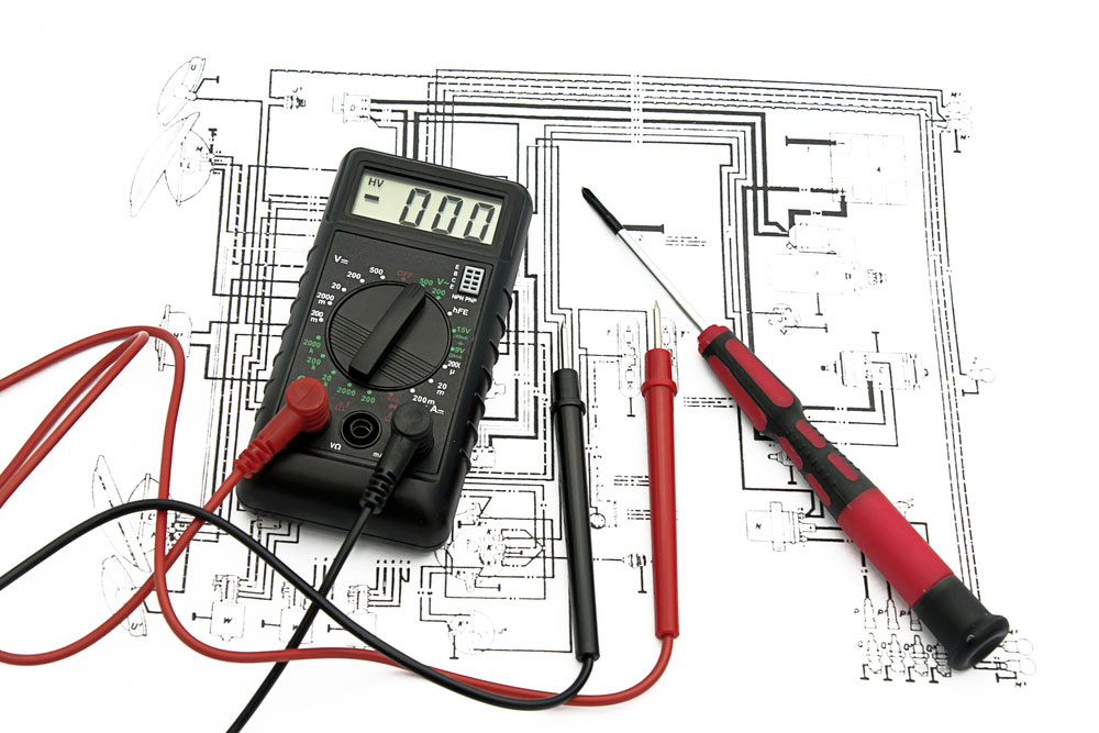 Electric circuit diagram and amp meter
Parts List
- LM317 Adjustable Voltage Regulator (IC1)
- LM358 Operational Amplifier (IC2)
- BC547 NPN Transistor (T1)
- 5mm LED x 3 (L1, L2, and L3)
- 8V Zenor Diode (ZD1)
- I¼-Watt +-5% Carbon 270-Ohm Resistor (R1)
- N4007 Rectifier Diode x 5 (D1, D2, D3, D4 and D5)
- ¼-Watt +-5% Carbon 2.2K-Ohm (R2)
- 2K-Ohm Potmeter (VR1)
- ¼-Watt +-5% Carbon 10K-Ohm (R3 and R6)
- 5K-Ohm Potmeter (VR2)
- ¼-Watt +-5% Carbon 22K-Ohm (R4 and R5)
- 5-Watt +-5% Carbon 0.2-Ohm (R7)
- ¼-Watt +-5% Carbon 4.7K-Ohm (R8 and R9)
- 20K-Ohm Potmeter (VR3)
- 220µF 40V Aluminium Electrolytic Capacitor (C1)
- 10µF 25V Aluminium Electrolytic Capacitor (C2 and C3)
- 1µF Ceramic Disk Capacitor (C4)
- 230V AC Power Input
- 15V-0-15V secondary transformer (X1)
- 2-Pin Connector Terminal (CON1)
- 12V, 7Ah rechargeable battery (CON2)
- 2-Pin Jumper Connector (J1)
- On/Off Switch (S1)
- Heat Sink for LM317 (S2)
Principle
If you’re looking for a far more complex circuit customization design, then this one is worth pursuing. Circuit design will charge 12V 7Ah sealed lead-acid batteries. It will charge your battery till it reaches its absorption voltage. Once it goes past the absorption stage, it will go into a floating stage to maintain the charge at its float voltage. The maximum float voltage is 14.3V, while the floating voltage is a maximum of 13.8V.
The circuit design's main components include a 15V-0-15V transformer(X1), an operational amplifier comparator (IC2), an LM358 adjustable voltage regulator (IC2), along with a few other parts. The 230V AC travels to the transformer, which steps the main voltage down. Subsequently, the first two IN4007 diodes rectify it (D1 and D2). Next, it will reach the LM317, which smoothens it.
We advise that you apply a heat sink to the LM317 voltage regulator to do the heavy lifting in the circuit. Furthermore, you must place the fourth capacitor (C4) near the operational amplifier comparator (IC2) if possible. You will need to use the 2-pin jumper (j1) for calibration.
Initially, when you set the charging voltage up, you’ll need to remove the jumper and reconnect after completing the calibration cycle.
Fast Lead Acid Battery Charger Circuit
Sealed lead acid battery
Parts List
- 1 Ohm Resistor x 2 (R1 and R2)
- 820 Ohm Resistor (R3)
- 560 Ohm Resistor (R4)
- 470 Ohm Resistor (R5)
- 500 Ohm Preset Potentiometer (P1)
- 1000uF 25 Volt Capacitor (C1)
- 330 n Capacitor (C2)
- 1uF 16 Volt Capacitor (C3)
- 500 mA Moving Coil Meter (M1)
- 12V 600 mA Secondary Mains Transformer (Tr1)
- On/Off Switch DPST (S1)
- 100 Ma Delayed Action Heat Sink
- 1N4001 Diodes x 6 (D1,D2,D3,D4,D7 and D8)
- IN41148 Diodes x 2 (D5,D9)
- Green LED (D6)
- L200 Regulator (IC1)
Principle
You can use this acid battery charge circuit customization to fast charge 6V and 12V lead-acid batteries. Additionally, this design features an automatic switch-off component. Thus it can work as an automatic battery charger circuit, or you can customize it into one. Furthermore, it has built-in protection against short circuits, polarity reversals, and temperature overloads.
Its current design appeals to time as it promotes rapid charging. However, it may result in reduced capacity and battery lifetimes.
This circuit uses an L200 voltage regulator to maintain the charging current. In turn, the first two resistors are there to shorten the current. However, the second resistor is only necessary if you are using a charging current above 0.5 A.
We do suggest that you implement a heatsink with the L200 regulator. You can either power the circuit using the mains or a 12V car battery. Nevertheless, if you plan to use a 12 V car battery, you should supply the secondary voltage of 18V. Additionally, you must raise the resistance of the first resistor (R1) to 1k Ohms. Furthermore, you must replace the first preset potentiometer with a 1K Ohm preset.
High Current Li-Ion Charger Circuit
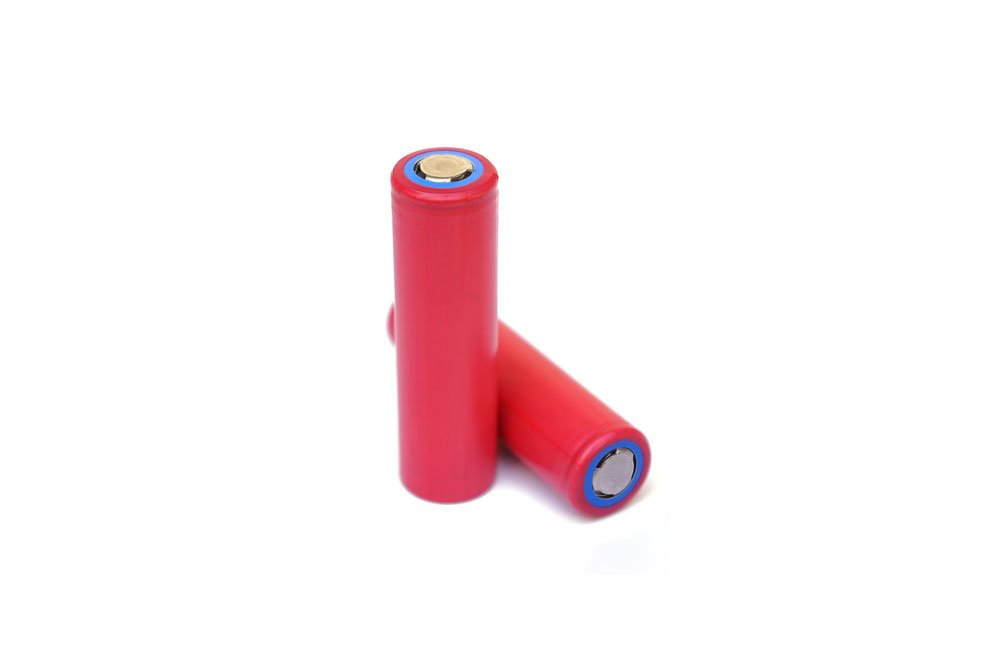 Red Lithium Ion Batteries in a white background
Parts List
- 7K Ohm Resistor x2 (R1 and R5)
- 240 Ohm Resistor (R2)
- 10K Ohm Resistor (R3 and R4)
- 10K Ohm Preset Potentiometer x 2 (P1 and P2)
- 6A4 - 400V 6A Switching Diode x 2 (D1 and D5)
- 1N4148 Diode (D2)
- 7V ½ Watt ZENER DIODE x 2 (D3 and D4)
- 741 Operational Amplifier for 12V input (IC1)
- LM338 Adjustable Regulator (IC2)
Principle
This battery charge customization is a little less taxing than the previous two. In fact, you can reuse some of the components from the previous customization to execute this one. This design features two important stages; the over charge-cut off stage(IC1) and voltage regulator stage(IC2).
If you’re going to use 12V input, you’ll need to use the 741 operational amplifiers for 12V input. However, if you plan to increase the voltage input with a 24V input, you will need a single LM321 operational amplifier (IC1).
The first preset potentiometer (P1) functions as a control dial to alter the charging voltage across the circuit. The second potentiometer helps prevent overcharging. When setting it up for the first time, do not connect the output battery.
Next, you will need to set the second pot (P2) to ground level. After that, you’ll need to adjust the first pot to get the best voltage level to charge your battery. You can also implement green and red LEDs to use as a status display.
Conclusion
The above guide explored how you can charge nearly every type of battery by customizing your battery circuit design. We included what we felt were five of the best customization functions and types. We ensured that there was a great mix of challenging and easy-to-build designs. Whether you’re a beginner or expert electronics hobbyist, you should find great value in the above text. Nevertheless, we hope that you’ve enjoyed reading this guide. Bookmark it and share it with all your friends. As always, thank you for reading.
Special Offer: Get $100 off your order!
Please email [email protected] for details.