Manufacturers make CD4511BE out of NPN bipolar transistor output devices and CMOS logic. Additionally, they have features like high noise immunity and low quiescent power dissipation the transistors combined with RCA CMOS.
Let us get into the details of its CD4511 description, like its pin configuration, features, equivalents, and applications.Contents
Special Offer: Get $100 off your order!
Please email [email protected] for details.
CD4511 Pin Configuration
The table summarizes the CD4511BE pinout.
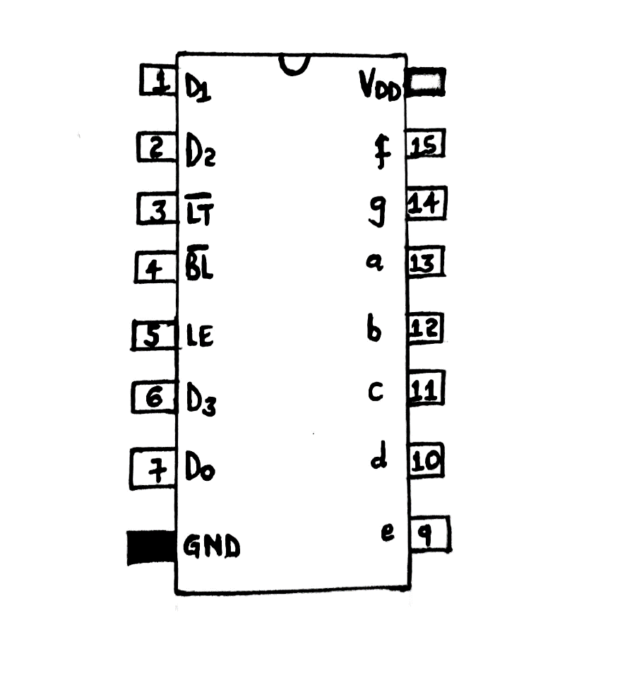
CD4511BE pinout diagram
Features/Technical Specification
The technical specifications and features of CD4511 BCD are as follows;
- First, it has an operating temperature range of -40°C to 85°C while the storage temperature ranges from -65°C to 150°C.
- Then, both the transition time and propagation delays are at a balance.
- It has a low power dissipation and zero hold time.
- Fourthly, it has a rigid structure and has the capability of lamp intensity modulation.
- Further, it has blanking inputs and a lamping test. There's also a latch input that can store a BCD code.
- In addition, it has a maximum operating supply voltage of 18V and a minimum of 3V.
- Manufacturers have also 100% tested its quiescent current of 20V.
- Its set-up time is 150, 70, and 40 respectively to 5V, 10V, and 15V voltages. Contrarily, it has a strobe pulse width with 400, 160, and 100ns at a respective 5V, 10V, and 15V.
- Finally, its maximum output current sourcing approximates 25mA. Additionally, a high input current of 1uA (the maximum) is 18 volts.
Special Offer: Get $100 off your order!
Please email [email protected] for details.
Equivalent
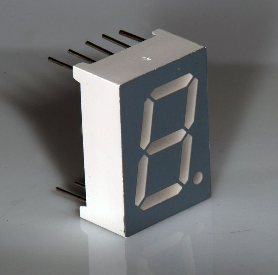
A 7-segment LED display component
Source; Wikipedia
Some CD5411 equivalents include 74LS145, 74LS48, CD4513, and CD4543. Alternatively, you can also use the options here; SN7448, SN54LS49, SN7LS48, SN54LS47, SN54LS48, SN5448, SN5556A, 7447, and 74LS477446.
We can also have;
- BCD to 7-segment decoder – 74HC46,47/48/49
- BCD to 7-segment decoder (for LCD) – 4054/4055/4056
- Decade counter with 7-segment display decoder – 4026
How to use the CD4511 BCD Decoder?
Using a BCD to a chip's 7-segment decoder requires you to follow the steps/explanation here.
- Begin by connecting the GND pin to the negative supply terminal. Additionally, attach the VDD pin to the positive supply terminal. The power supply voltage can be anywhere between 3V to 15V, even though other chips can withstand 20V. However, check your datasheet to ascertain the exact values of the voltage requirement.
- Next, you feed the number you want to display in binary format in pins D0-D3.
- Then, connect your seven-segment LED display to the output pins (pins A to G).
- The lamp test pin will further test the working of all display segments. Therefore, set it on a high level for regular operation and low when trying the seven-segment displays.
- When low, the blank test pin turns off all display segments. Keep it high during normal operations. It can also use PMW (Pulse-width modulation) to control the display's brightness.
- Finally, the store/ latch enable or LE pin stores the current value. Set the store pin low to operate normally. When you set a high pin, you'll constantly display the last data despite changes in the BCD inputs.
How to Build a 4511 BCD to 7 Segment Decoder Circuit?
For the section, we'll discuss an application circuit that uses CD4511.
Example circuit
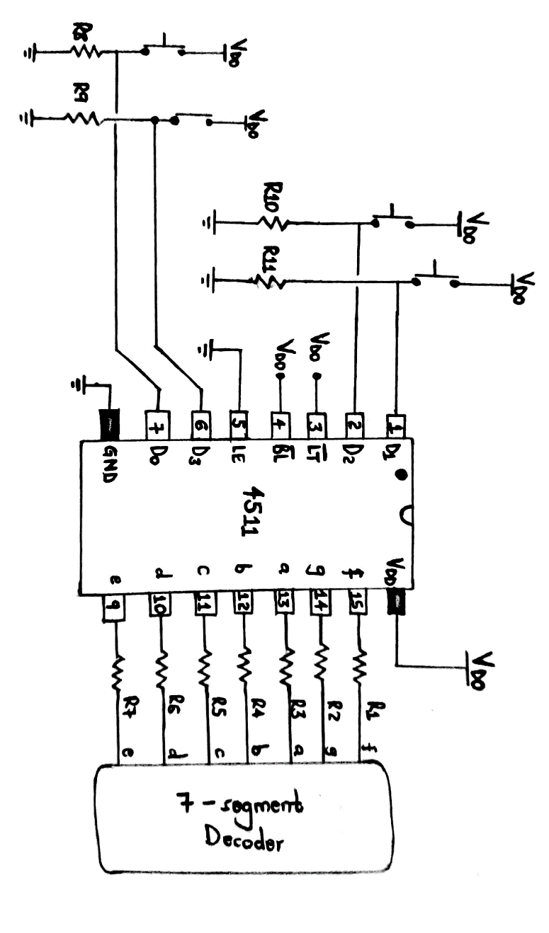 Circuit diagram of CD4511 BCD to a 7-segment decoder
 Components needed
- Four pushbuttons,
- Seven resistors (R1 to R7) each 1kΩ,
- A 4511 chip, for example, CD4511BE,
- Four resistors (R8 to R11), each being 10kΩ, and
- A 7-segment display with a common cathode like an LSHD-5503.
Briefly, the CD5411 chip controls the 7-segment production such that it turns each segment on, thus displaying the correct numbers.
The few resistors or a resistor pack also helps in connecting the 7-segment display.
Moreover, you can modify its input with the circuit to create a stopwatch. The modification turns the information into an output counter that counts seconds.CD4511 application
You can find CD4511 in the applications listed below.
- In driving incandescent displays/ LED lighting,
- Low voltage fluorescent display,
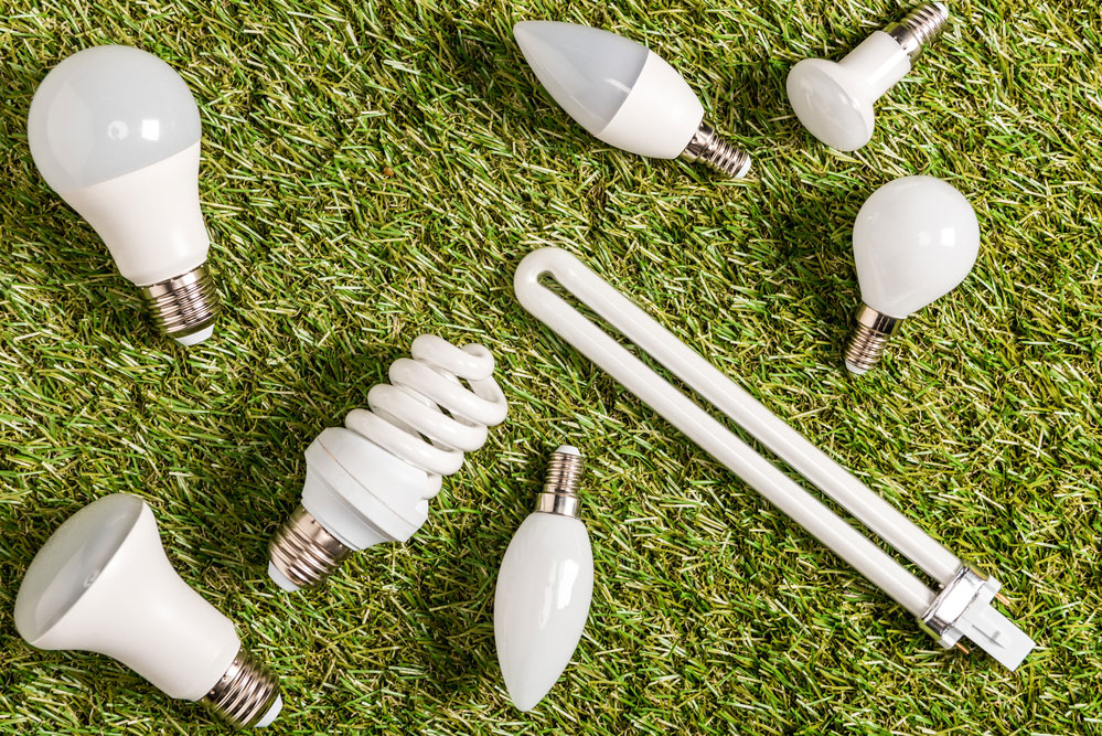
(fluorescent lamps)
- In multiplexing and displaying multiple signals,
- In-display drives of cockpits, calculators, computers, counters, etc.
CD4511BE is a 7-segment LED latch decoder driver to CMOS BCD found in most semiconductor companies. Further, it has a single monolithic structure, and it's in a 16 pin DIP in its original packaging. Most of its applications involve driver LEDs and a few other displays.
To find out more about CD4511BE, kindly contact us.Special Offer: Get $100 off your order!
Please email [email protected] for details.