When you think about choosing a transistor for your project, chances are you might get scared about choosing the wrong one. Or, you simply don’t know which one to choose.
Well, if you’re in such a situation, you’re in luck.
This article will introduce you to one of the most effective transistors: the BC107.
The BC107 is a low-power transistor belonging to the NPN bipolar junction type of transistor. Also, it comes in a TO-18 metal case package.
So, get ready to learn everything about this transistor and the several circuits you can build with it.
Let’s go.
Contents
- Pin Configuration of the BC107 Transistor
- Features of BC107 Transistor
- Alternative Transistors
- Where to use the BC107
- BC107 Applications
- How to Choose a Suitable Transistor
- Know-How Transistors Work
- Understand the Key Characteristics to look out for
- Learn How to Connect Transistors
- Circuit Examples Using BC107
- Crystal Tester Circuits using BC107
- Dancing Light Circuit Using BC107
- Schmitt Trigger Circuit Using BC107
- Rounding Up
Special Offer: Get $100 off your order!
Please email [email protected] for details.
Pin Configuration of the BC107 Transistor
Like other transistors, the BC107 transistor has three pinouts (terminals):
| Pin Number | Pin Name | Description |
| Pin 1 | Base | The base handles the biasing of the transistor (Turns the transistor ON/OFF). |
| Pin 2 | Emitter | The emitter handles the transistor’s gate voltage drain, and it’s usually connected to the ground. |
| Pin 3 | Collector | The collector handles the flow of current, and it’s usually connected to the load. |
Features of BC107 Transistor
Here are the key features of the BC107:
- It’s an NPN transistor with a small signal
- It comes in a TO-18 metal case package
- The VCEO (collector-emitter voltage Vces) of the BC107 is 45V
- Its HFE (continuous current gain) is a maximum rating of 450
- The VBEO (base-emitter voltage) of the BC107 is 6V
- The rating of BC107 IC (continuous collector current) is 100mA
- The VCBO (collector-base voltage) is 50V
Alternative Transistors
BC547, 2N3904, BC549, BC177, 2N5581, 2N706, 2N2369, BCW65, MPSL51, D27Z, BCW65, MPSL51, and BCW65.

Multiple Transistors
Special Offer: Get $100 off your order!
Please email [email protected] for details.
Where to use the BC107
As we mentioned earlier, the BC107 is an NPN transistor with a low signal. And it mainly works in signal processing circuits and television receivers because of how it works with low noise.
Though there are more modern replacements for the BC107, you can still get a BC107 transistor in the market because of how good it is at such applications.
BC107 Applications
Before we go into the applications, it’s worth mentioning that the BC107 can only allow a maximum current of 100mA when entirely biased. Thus, connecting loads that require more than 100mA might damage this transistor.
With that out of the way, here are the different applications of the BC107:
- Works in driver module applications such as LED drivers and relay drivers
- You can use the BC107 to make a Darlington pair
- It also works in amplifier module applications such as signals amplifiers and audio amplifiers

Audio Amplifier
- Works in portable devices
- Also works in consumer electronics

Consumer Electronics
- You can use it for power management applications
- Works for industrial purposes
- You can also use it for signal processing applications
How to Choose a Suitable Transistor
If you’re having trouble selecting a transistor for your project, here are a few tips to help you choose the suitable transistor:
Know-How Transistors Work
Transistors are responsible for amplification or switching in various circuits. So, the first step to deciding the transistor you need is knowing how they work.
If a transistor works as an amplifier, it’ll transform a low input current into a high output current. Thus, amplifying the current and delivering it to the output.
On the other hand, if it works as a switch, the transistor would use a low input current to drive a higher current in another area. Thus, allowing the lower current to switch on the higher current.
Understand the Key Characteristics to look out for
Before getting a transistor for your project, you have to understand some essential characteristics. These characteristics include:
Collector Current
Note that power transistors and normal transistors have different maximum collector current values. While the power transistor’s collector voltage is in milliamps, normal transistors have theirs in amperes.
Always refer to your transistors datasheet to know the maximum collector current. So, don’t exceed the maximum value.
Saturation Voltage
For the transistor to enter saturation mode, you must apply a specific voltage between the emitter current and the collector.
Refer to the datasheet to find the exact voltage required (VCE).
Breakdown Voltages
It’s essential to know the two required breakdown voltages—collector-base and collector-emitter voltage breakdown. Thus, you must not exceed this during operation to avoid damaging the transistor.
Current Gain
Current gain HFE is an essential feature of an amplifier-based transistor. Also, there are different current gains for different applications. Thus, you should always check the current gain value (β) before choosing.
Material and Polarity
Most transistors use silicon as a major semiconductor material. Though silicon has excellent properties, some other transistors come with different semiconductor materials with different properties.
Also, whether the transistor is NPN or PNP determines the polarity of the voltage output. NPN transistors are more common because most applications need a positive voltage output.
Learn How to Connect Transistors
Before connecting any transistor and applying voltage, check its datasheet to ensure you have the right operating voltage range for the right transistor. Also, make sure you know which leg is the collector, emitter, and base.
Circuit Examples Using BC107
Now, let’s look at some circuits you can make using the BC107. The circuits we’ll discuss here include the crystal tester, dancing light, and Schmitt trigger circuits.
Crystal Tester Circuits using BC107
Crystals are expensive materials, and you can’t measure them with a standard multimeter. However, if you want to test if a crystal is good or bad, you can simply build a crystal tester circuit.

Crystal
Crystal helps to generate radio frequencies and also works in clock signal controllers. Also, you can find them in quartz watches and digital circuits.

Quartz Watches
This crystal tester circuit can test crystals from 100 kHz to 900MHz. Plus, it’s not expensive and is easy to build. Here is the circuit diagram:
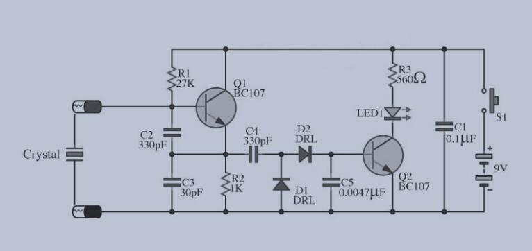
Crystal Tester Circuit Diagram
Source: Wikimedia Commons
The main component of this oscillated circuit is the BC107 (transistor Q1). Plus, it generates a frequency when you place a crystal on the socket connected to the base current pin of the transistor.
So, when you press the switch of this circuit, it allows current flow from the battery to the circuit. Also, it allows the oscillated signal generated from Q1 to move to C4.
Additionally, the oscillator signal will constantly change. Thus, the D1 and D2 will smoothen the current.
That’s not all.
The signal will also move through C5 (which helps to smoothen the signal). Once this happens, the positive voltage across C5 will trigger a bias current that’ll flow to the Q2 and light up LED1.
Moreover, the R3 will limit the current flowing through to the LED1 to stop it from passing 20mA and damaging the LED.
Thus, LED1 will only illuminate when Q1 works. On the other hand, the Q1 needs a quality crystal to build frequency. So, with this, it’s easy to measure any crystal.
Dancing Light Circuit Using BC107
Here, we have a dancing light circuit configured as a free-running oscillator, and it’s also a free-running oscillator. Check out the circuit diagram below:
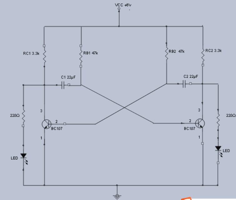
Dancing Lights Circuit
Source: Wikimedia Commons
This circuit generates a square waveform with two transistors alternately switching between ON and OFF states. What’s more, the switching process also allows the LED to turn ON and OFF alternatively. So, the two LEDs can’t be ON at the same time. Thus, creating the dancing lights effect.
Schmitt Trigger Circuit Using BC107
The Schmitt trigger is a bistable multivibrator coupled with an emitter without its cross-coupling. Also, it’s a comparator that converts analog waves to square waves. Thus, we can also call this circuit a squaring circuit. Here’s the circuit diagram:
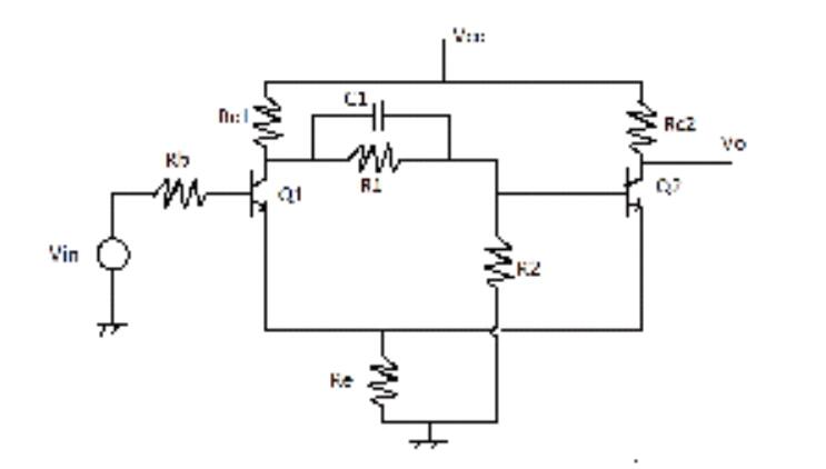
Schmitt Trigger Circuit
Source: Wikimedia Commons
For this circuit, the output will go high when the input’s amplitude goes above a set level which we call the upper threshold point (UTP). Conversely, the output will decrease when the input signal’s amplitude goes below a set level (lower threshold point).
Also, if the Q1 does not receive a signal, it’ll stay in an off state while Q2 remains in a saturation state. Additionally, when the amplitude of the input signal reaches the upper threshold point, Q1 will run on while Q2 turns off. Thus, raising the output to VCC. However, Q1 requires a minimum voltage to stay on; otherwise, the transistor will go back to an off state.
So, when the input signal goes below that minimum clamping voltage, it turns on Q2, turns off Q1, and drops the output voltage.
Rounding Up
There are a few things to note before we conclude this article. First, transistors are divided into two main categories, which include bipolar junction transistors (BJTs) and field-effect transistors (FETs).
Also, there are two kinds of transistors based on regions, and these types include the –p-type and the n-type.
Additionally, BJTs consist of two p-n junctions and can use two configuration types, the NPN or the PNP. You’ll always find three terminals on BJTS (base, emitter, and collector). You can also find three terminals on FETs, but they can only be p-type or n-type.
That rounds up this article. If you have any questions, feel free to ask us, and we’ll be happy to help.
Special Offer: Get $100 off your order!
Please email [email protected] for details.


