Let's say you have an idea and recommended components like an Arduino to accompany it. What’s remaining is a platform to construct your project idea and bring it to life. The medium/platform you are looking for is an Arduino Protoshield.
Protoshield elements facilitate prototyping, allowing an easy and fast connection between an Arduino and breadboard.
In this post, we will learn how to assemble an Arduino Protoshield while looking into its features and kit constituents.
Contents
What is an Arduino proto shield?
An Arduino proto shield is a prototyping shield that can help you design a customized circuit. It is often ideal for soldering an SMD or TH ICs on the prototyping area before testing them on your Arduino board.
Special Offer: Get $100 off your order!
Please email [email protected] for details.
Arduino protoshield Features
Some of the features and characteristics of Arduino protoshield are as follows;
- First, it has components like a USB jack, resistors, LEDs, switches, and buttons).
- Then, it has a USB type B connector and a breadboard-style prototyping area.
- Thirdly, you can easily find the 5V, 3.3V, and ground power rails anywhere on the breadboard.
- Also, it has a dual ISP breakout for easy stacking and programming.
- It also has Arduino I2C and UART port pin breakout, enabling external communication interfacing.
- Besides having several through-hole sizes to fit most parts, it also has a large 0.1in pitch prototyping area.
- Lastly, it is compatible with Arduino UNO.
- Components are included in the kit.
An Arduino Protoshield kit usually consists of the following components.

How Do I Assemble It?
Now that we have the electronic requirements let us assemble the Arduino Protoshield.
Step One
- First, soldering the Red LED to the power socket outline holes and ensure the outline on the board matches the flat side of the LED.
- Next, solder the green LED, but this time on the holes in the Pin13 board outline.
Note: The long leg on the LEDs is the anode, while the short leg is the cathode. The cathode goes into the flat edge of the board's semi-circle.
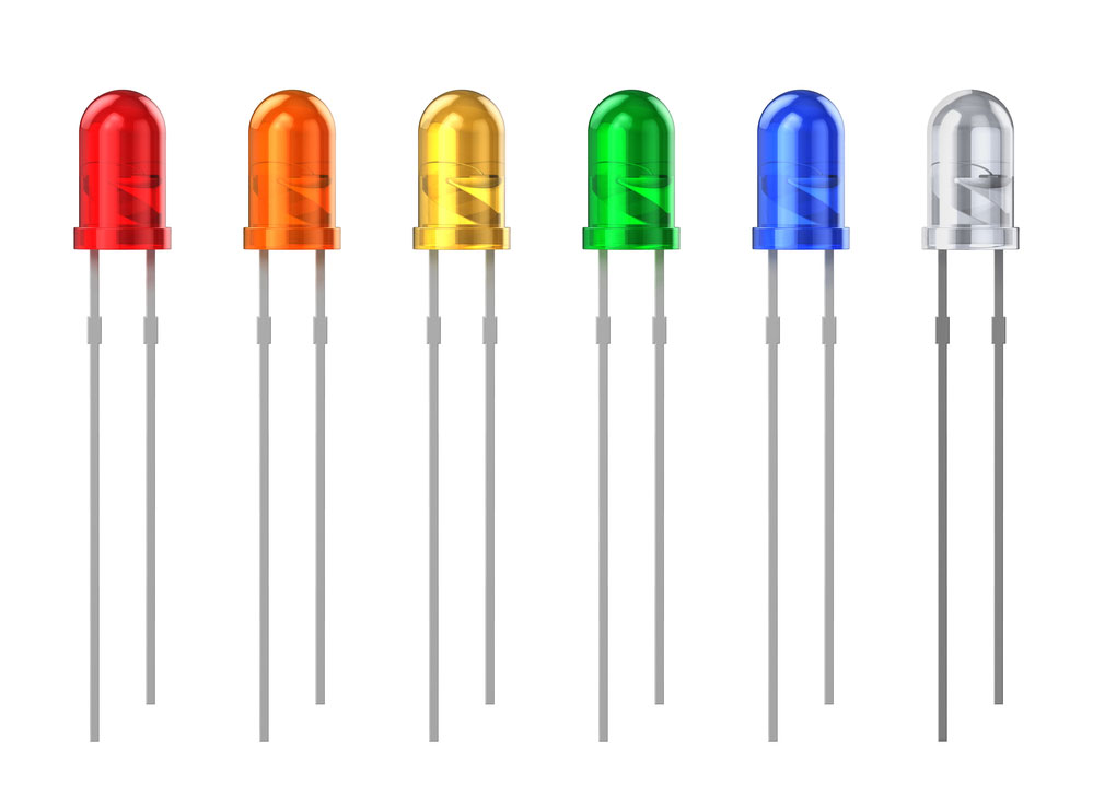
(LEDs)
- Afterward, solder the two resistors labeled R2 and R1.
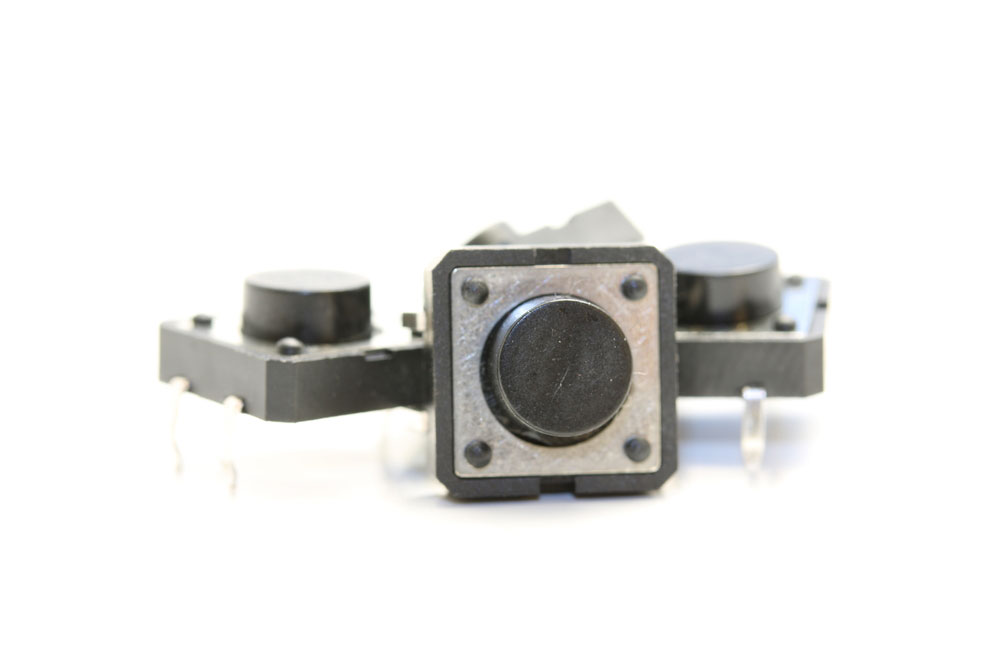
- Then, solder the ISP header and the reset button. It is often advisable to insert the reset button before the ISP header for easy connection.
- The mini switch buttons should fit perfectly in the square footprints with circles in the middle.
Step Two
When soldering in the headers, ensure they straightly align with one another for effortless plugging into the Arduino.
(Electronic components, headers)
Commence by plugging in the 6-pin header and then the 8-pin header.
Step Three
Solder the male and female connectors into the JC# through-hole pins.
However, note that if you are an Arduino, you will not solder ADC7 and ADC6. Contrarily, when using a Seeeduino, you’ll only solder ADC7 and ADC6. Furthermore, you’ll use jumper wires to achieve the pin connections since it helps in keeping the Protoshield versatile and reusable.
Step Four
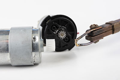
Now, place into the USB port a USB connector, then attach the potentiometer in the 80mil holes on the board.
You can now place the bottom left power pins per your project's requirement.
The look above is complete but has an empty prototyping area. You can choose to solder a large variety of Dual in-line package (DIP) sized chips.
Alternatively, you can add a breadboard on top of the breadboard area if you intend to reuse the shield. The boards can be self-adhesive breadboards that perfectly stick to the prototyping area. However, the procedure will cover the GND and 5V buses, even though you may have access to the headers.
The shield has a new 6-pin header labeled BlueSMiRF at the Protoshield’s edge. You will need a BlueSMiRF Bluetooth modem to match the header’s pinout. Then, directly wire the modem to the Arduino serial pins (D1 and D0).
A BlueSMiRF normally operates by replacing the need for serial cables.
That’s it! You have finished constructing your Arduino Protoshield. You can further use the shield to prototype projects like;
- A 555 timer,
- Weather station receiver,
- Temperature controller/monitor,
- 4-bit maze,
- Joystick control of servo motors,
- Ultrasonic range finder tape measure, and
- Arduino USB host.
Conclusion
We hope you have as much fun as we have while building our Arduino Protoshield. The steps are elaborate. Therefore, it should be simple to put the project idea together.
However, if you need any clarifications or have queries, kindly reach out to us.
Special Offer: Get $100 off your order!
Please email [email protected] for details.