Contents
- What is an Analog Joystick?
- Pin Description
- How Does the 2-axis Thumb Joystick Module Work?
- Gimbal Mechanism
- Potentiometer
- Analog Joystick Interfacing with Arduino
- Equipment Required
- Wiring Joystick Module to Arduino
- Arduino Code
- Code Explanation
- Analog Stick Replacement
- Step 1: Controller
- Step 2: Opening the Handle
- Step 3: Opening the Button
- Step 4: Removing the Battery
- Step 5: Disassemble the
- Step 6: Completing Disassembly
- Step 7: Left Analog Stick
- Step 8: Replacement
- Problems with Analog Joystick
- Summary
What is an Analog Joystick?
Also known as a thumbstick or control stick, the analog stick is a controller input device for two-dimension input. It features two potentiometers connected, X-axis- for horizontal movement and Y-axis for vertical movement. Besides, both X-Y coordinates pinpoint just as with the normal geometry positioning the stick impeccably. In addition, it comes with top-notch switches, making it a perfect fit for RC cars, robot control, and retro gaming.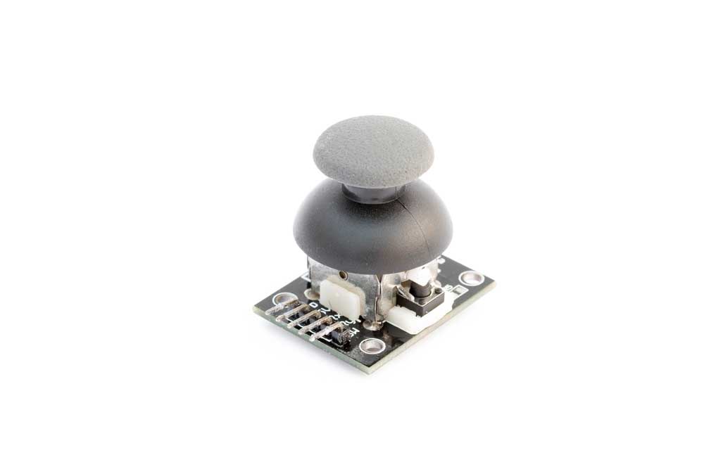
Joystick Module for Arduino projects
Pin Description
Pin 1, 5 – GND and VCC- Supplies +5V voltage and ground module terminal to Joystick
- Positive supply terminal of Module. Provides 0 volts to VCC analog output voltage in accordance with the movement of Holder in X-direction (axis)
- Voltage is proportional to Y-axis. Provides 0 volts to VCC analog output voltage in accordance with the movement of Holder in Y-direction (axis).
- Features only one demonstrative button
- It connects to the VCC through a resistor once you haven’t pressed the switch. Once you press the switch, it connects to the Ground.
Special Offer: Get $100 off your order!
Claim your $100 discount by sending an inquiry today. Act now to save on your next project!
Please email [email protected] for details.
Please email [email protected] for details.
How Does the 2-axis Thumb Joystick Module Work?
Basically, the joystick’s basic idea is to convert the stick's station on two axes into automated info that Arduino can develop. Nevertheless, translating can be a bit hard; however, thanks to its design, it has a Gimbal Mechanism and two potentiometers.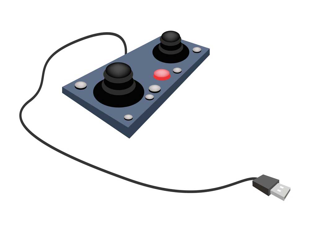
The joystick on White Background
Gimbal Mechanism
By rotating the joystick, the thumb knob swings the thin pole on the two rotatable and well-positioned handles (Gimbal). Hence, one handle permits movements up and down (Y-axis) while the other is left and right (X-axis). Once it tilts the stick from side to side, it makes the Y-axis shaft forward and backward. In addition, once you move the stick diagonally, both shafts will pivot.Potentiometer
The potentiometer connects to the joystick shaft, which determines the pole's location as analog interpretations. Once you move the fitted slide, it swings the connected potentiometer arm. It means pushing the rod forward moves the potentiometer arm towards the track end. Additionally, pulling it back towards your side turns the contact arm to the other side.Analog Joystick Interfacing with Arduino
In this circuit, we will interface Joystick with Arduino by controlling four LEDs according to the Joystick’s movement. Furthermore, to ensure that the 4 LEDs exemplify the joystick shaft movements, we will place them in a way that displays the direction. Besides, the Analog joystick features a drive button, which we can use for different objectives or let it remain inactive. Again, its switch has an LED linked; therefore, the sole LED turns ON by pressing the switch.Equipment Required
- LEDs – 5
- Resistor: 100ohm -3
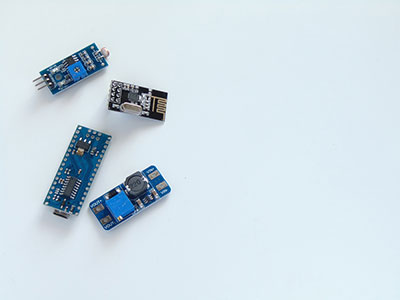
- Joystick Module
- Arduino UNO
- Breadboard
- Connecting wires
Wiring Joystick Module to Arduino

Wiring Joystick to Arduino UNO
To determine X and Y joystick coordinates, we will have to link the two joystick analog outputs to Arduino analog pins. Hence, we will connect VRx in our Arduino board to the Arduino AO analog pin while the VRy to the Arduino A1 analog pin. In addition, we will connect the joystick SW pin to Arduino D8 digital pin. It will help us know if the joystick knob is already down. Additionally, the joystick requires power. Therefore, its VCC pin links to the Arduino 5V terminal while the GND pin links to the Arduino GND terminal.Arduino Code
Within the two inputs (analog and digital), we will read the measurements and display the outcomes on the serial monitor.
Code Explanation
The delineation begins by resetting the Joystick module connection within the Arduino. Likewise, the VRy and VRX pins connect to #1 and #0 analog pins, while the SW pin connects to Arduino Pin #8.


Analog Stick Replacement
Step 1: Controller
Begin by removing the four 6.0 mm screws used to protect the controller rear cover using the Screwdriver. Meanwhile, don’t use much force to loosen the screw. It might make the removal impossible by causing permanent damage to the threads.
Joystick
Step 2: Opening the Handle
Start with the left handle, where you will introduce an opening by pinching the controller’s left handle. Consequently, shove an opening using plastic equipment, sliding it up toward the joystick. Pop open the covering by pulling down the pincher. Finally, use the same steps to open the right handle.Crack-open the covering near the option and share buttons by shoving plastic opening equipment on the case splitting. Moreover, ensure that the controller part attaches to the motherboard ribbons and splits its plastic covering. On the structure, you will find three small fragments; one Gray reset button and two activate springs. Their work is to control the project field and avoid loss.

Gaming console and controller
Step 4: Removing the Battery
Using your fingers, disconnect the motherboard ribbon that connects both sides of the controller and pull it out gently. Again, when reconnecting, ensure the cable alignment faces the right position.Step 5: Disassemble the
Using the screwdriver, take out the screws underneath the battery retainer. Also, detach the touchpad ribbon, which connects to the motherboard gently. Furthermore, you will find a touchpad ribbon that connects to the motherboard that tosses to loosen and tightens. Afterward, you will need to remove the plastic tray from the motherboard to reattach the ribbon when reassembling. Sensibly extricate the system board from the front cover.Step 6: Completing Disassembly
After disassembling the controller, you will have the Rear cover, front cover, and system board assembly.Step 7: Left Analog Stick
To prepare the circuit board for the solder work, use the “helping hands” or similar tool that will hold steadily. Next, remove the solder using flux and a desoldering wick. After desoldering all the contacts, you can then remove the old joystick. Besides, you will need to remove the solder; hence, you might have to hold a little on the joystick when using the wick or to melt the solder.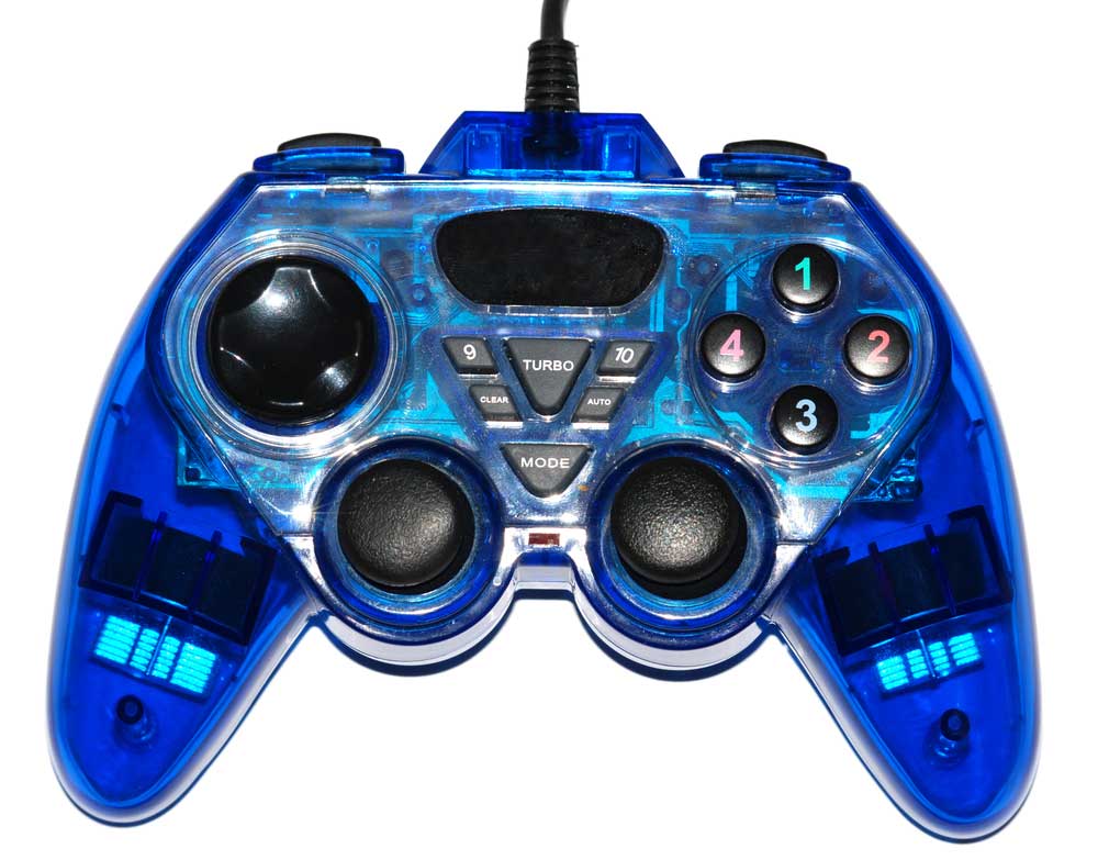
Video game joypad
Make sure the joystick replacement resembles the original version. Clear the holes using small drill bits or hypodermic needles. Likewise, ensure the holes are clear with no traces of old solder. Besides, the printed circuit board has flux – a molten-looking substance used for desoldering that you can use.Step 8: Replacement
Connect the new joystick, ensuring it fits the circuit board appropriately, aligning the contact lineup with motherboard holes. After replacing the analog stick, what is remaining is cleaning up the former flux using some isopropyl alcohol.Problems with Analog Joystick
The analog joystick system has a couple of significant problems. First, the systems lack an accurate analog-to-digital converter; therefore, the crude analog-to-digital conversion process inaccurately compromises its sensitivity. Secondly, to enable the joystick system to regularly “survey” to define the stick position, the microcontroller must dedicate much power during the process.Summary
The Analog joystick is among the best controllers capable of creating various activities. Its two-dimension input makes it the best device for a pointer movement controller. Besides, their top-notch shifts make it an ideal module for retro gaming, robot control, controlling camera movements, and much more.Special Offer: Get $100 off your order!
Claim your $100 discount by sending an inquiry today. Act now to save on your next project!
Please email [email protected] for details.
Please email [email protected] for details.